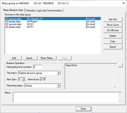
The Relay Group Properties Command in the Main Window lets you review and edit the properties of a relay group. Objects within a relay group include relays, fuse, reclosers and logic schemes. Within the relay-group dialog box, you can (1) edit the parameters of protective devices and logic schemes that are within the group, (2) add new protective devices and logic schemes to the relay group, (3) remove existing protective devices and logic schemes from the group or (4) export relay parameters to a disk file. You can also review and edit coordinating pairs of which the relay group is a member.
To execute this command you must first select the relay group of interest.
Please see Section 5.1 RELAY DIALOG BOXES for explanation of relay, fuse and recloser parameters. Please see SECTION 6 LOGIC SCHEMES for information on logic schemes.
TO REVIEW OR EDIT THE PARAMETERS OF A RELAY GROUP:
1. Select a relay group.
Click the left mouse button once on the relay group you want to review or edit.
The relay group symbol will turn dotted red when selected.
2. Select the Relay | Relay Group Properties command.
A dialog box will appear. The ‘Relay/Breaker Data’ page is on top initially. The list box shows a list of all the relays, fuses and reclosers that are within the relay group. The first device is highlighted.
You can select multiple devices in this list (with mouse clicks with the <Ctrl> or <Shift> key held down) when using the “Show Curve”, “Delete”, “Copy” and “Export” functions.

3. Enter breaker trip logic.
When the trip-logic is set to “Fastest device in group”, OneLiner will compute the trip time as the fastest time among all the tripping relays and logic schemes in the relay group. This is how OneLiner worked prior to V12.
In V12 and later, you can alternatively select in this list box one of the logic schemes. In this case, OneLiner will compute the trip time based solely on the operating time of the selected logic scheme.
Note: if you specify a logic scheme for relay-group trip and the scheme is later deleted or becomes otherwise unavailable, the logic of ‘Fastest device in group’ option will automatically be applied in trip time calculation.
4. Enter the breaker interrupting time in cycles.
The breaker interrupting time is the time between energization of the trip circuit to the extinction of the arc on the primary contacts. The program uses this value for stepped-event simulations.
5. Enter the reclosing logic and reclosing intervals for lines and switches.
Set the number of operations to 1 if there is no reclosing. Set it to 2 if the line/switch recloses once, and so on. The maximum number is 4.
When the number of operations is greater than 1, you must enter the reclosing intervals (in seconds) in the edit boxes provided. The reclosing interval is the time lapse between the opening of the line/switch terminal and the subsequent reclosing operation.
6. Enter a memo.
The memo is for any notes you wish to keep for this relay group. It can have up to 512 characters.
7. Press the button to the right of the text area to enter one or more tags and user-defined data fields for this relay group.
The tags are for organizing objects that are related for some purpose. Please see documentation for Network | Apply Tag for more information.
The user-defined data fields are customizable in File | Preferences dialog box.
TO GET INFO ON A PROTECTIVE DEVICE:
1. Select a single device to review or edit.
2. Press Get Info to review or edit the device parameters.
Note: The Get Info button is enabled only when one, and only one, item is selected in the list box.
A dialog box will appear listing the parameters of the relay, fuse or recloser you selected. Please refer to SECTION 5 RELAY DIALOG BOXES for more information on the dialog boxes of these devices.
TO SHOW RELAY, FUSE OR RECLOSER CURVES:
1. Select one or more devices in the list and press Show Curve.
Note: You can select up to 16 overcurrent devices or 1 distance-relay.
The Relay Group dialog box will disappear. The OC Curves Window or the DS Relays Window will appear showing you the curves or characteristics of the selected devices.
TO TOGGLE THE ON/OFF-LINE STATE OF DEVICE(S):
1. Select one or more device in the list and press On/Off-line.
The indicator to the right of the relay ID will change to reflect the new state. The in-service devices are always listed before the out-of-service devices.
TO ADD A RELAY, FUSE OR RECLOSER TO A RELAY GROUP:
1. Press the Add button. A dialog box will ask you want you want to add.
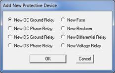
Mark one of the radio buttons and press OK.
If you selected New Distance Phase or Ground Relay, a “Select a Distance Relay Type” dialog box will appear. The type name is generally the relay's actual trade name. If the relay type name you are seeking is not in the list, you must first exit OneLiner and add the new relay type to the distance relay library using the Distance Relay Editor.
Note: Relay types with names that end with “__”, e.g., “SEL331G__”, are hard coded and therefore cannot be added or removed with the Distance Relay Editor.
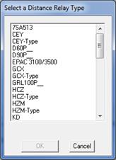
Highlight a distance relay type and press OK.
A dialog box for the distance relay will appear. Please refer to section 5.6 DISTANCE GROUND RELAYS for more information on the distance relay dialog box.
If you selected New OC Relay, New Fuse or New Recloser in the “Add New Protective Device” dialog box, a dialog box for the relay, fuse or recloser will appear. Please refer to sections 5.2 OVERCURRENT GROUND RELAYS through 5.5 RECLOSERS for more information on these dialog boxes.
TO IMPORT PROTECTIVE DEVICE DATA TO THE RELAY GROUP:
1. Press the Import button. The Import Relay Data wizard will appear to guide you through the process of creating a device with imported relay data.
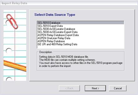
2. Select a data-source type.
Relay data can be imported from the following data sources:
• SEL-5010 Database: Setting data in an SEL-5010 MDB database file.
• SEL-5010 Export Data: Setting data in an MDB file exported from the SEL-5010 program.
• SEL-5030 AcSELerator Database: Setting data in an SEL-5030 RDB database file.
• SEL-5030 AcSELerator Export Data: Setting data in text files exported from SEL-5030 AcSELerator. There are usually multiple text files, one for each setting group. These files must reside in a single directory.
• ASPEN Relay Database Export Data: Setting data in ASPEN Relay Database’s text data format (.TXT file). See appendix in ASPEN Relay Database User Manual for the setting-file format specification.
• ASPEN OneLiner Relay Data: Setting data in OneLiner’s relay text data format (.RAT file). See SECTION 10 RELAY DATA FORMAT (Legacy) for the format specification. The location information in the .RAT file is ignored.
• ASPEN Relay Database: Setting data in the ASPEN Relay Database.
• ENOSERV Database: Setting data in the ENOSERV PowerBase. (Note: This data source is available only when PowerBase software with correct license is also installed on the same computer.)
• GE UR and 469 Relay Setting data.
• Toshiba GRL100 Setting Export data.
• ABB XRIO Setting Export
• NXTPhase L-PRO Offline Settings
• IPS RSEI Setting Export (NOTE: This import option is in experimental stage in OneLiner version 14.7 release.)
Click on one of the data types in the list box and press Next.
3. Select a Setting Scheme to Import
When the import from a data source that contains multiple setting schemes, such as the SEL-5010 database, the Wizard will display a screen that lists all the available setting schemes. The picture below shows such a list. You can make use of the dropdown list box in the upper right corner in this screen to show either all the schemes or just the schemes of certain SEL relay type.
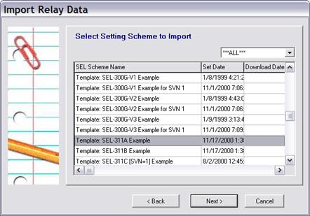
Click on a setting scheme in the data grid and press Next.
4. Link imported OneLiner relay to the data source.
The Setting Summary page will appear with key information about the setting you are trying to import, such as Manufacturer, Relay types, and others.
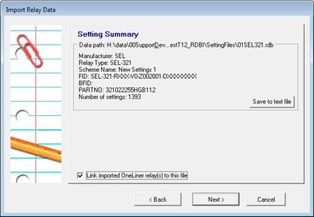
Mark the ‘Link imported OneLiner relay(s) to this XXX’ check box to store the data source details you have selected in the wizard so far in OneLiner where XXX can be ‘file’ or ‘data record’ depending on type of the chosen data source. Please refer to sections 5.2 OVERCURRENT GROUND RELAYS through 5.6 DISTANCE GROUND RELAYS for more details on the link between OneLiner relay and external setting data source.
Note: The program may display error message “Relay type not supported” when importing some setting files. This error tells you that the settings you are importing from the external data source did not match any of the known relay types in the program import logic library. Press the button Save to text file to create a copy of the relay setting data and send it to ASPEN Tech Support with your request to update the program library to include this new relay type.
Press Next when ready.
5. Select Relay Elements to Import.
The Select Relay Element page displays list of all the overcurrent and distance protection elements that are enabled in the selected active setting group.
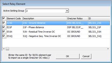
Mark the check box next to the elements you want to import.
Enter desired OneLiner relay ID in the ID column cells.
Note: To import a pair of inverse time and instantaneous/definite-time overcurrent elements with compatible operating quantities and directional control settings as a single OneLiner relay, enter the same ID for both elements.
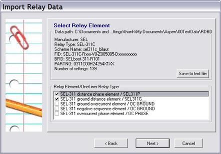
Note: When importing setting from some relay types, the program may display the legacy Select Relay Element page as shown in this picture:
Press Next to commence data import.
Note: When the data source contains settings for multiple groups, additional dialog box will appear to let you select the setting group you want to import.
Relay dialog boxes that correspond to the selected relay elements will appear one after another. Please refer to sections 5.2 OVERCURRENT GROUND RELAYS through 5.6 DISTANCE GROUND RELAYS for more information on these dialog boxes.
6. Verify imported relay settings in relay dialog box. Enter additional parameters when prompted. Press OK to close the dialog box.
The newly imported devices will appear in the list of devices in the relay group.
TO DELETE RELAY, FUSE OR RECLOSER:
1. Select device(s) you want to remove and press "Delete".
The device will be removed from the relay group. Its name will disappear from the list box.
TO COPY RELAY, FUSE OR RECLOSER TO THE CLIPBOARD:
1. Select device(s) you want to copy and press "Copy".
The program will copy the data of the selected device to the clipboard.
TO CREATE A NEW RELAY, FUSE OR RECLOSER BY PASTING DATA FROM THE CLIPBOARD:
1. Press the Paste button.
Note: The Paste button is enabled only where there are relay data in the clipboard.
The program will create a device using data from the clipboard. The new device will appear in the list.
TO PLACE A RELAY, FUSE OR RECLOSER IN A RELAY GROUP:
You can place in the relay group relays from the “holding tank”. The devices in the holding tank were put there by the Relay | Import Relay command when the relays’ location information (in the .RAT file) is missing or invalid.
1. Press the ‘Place’ button. A dialog box will appear with list of relays in the holding tank.
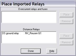
2. Highlight an entry and press Place to place the relay in the selected relay group.
Alternatively, press Remove to erase the relay record from holding tank.
3. Repeat step 2 for all the relays that you wish to place or remove. When finished, press Done to close the dialog box.
TO EXPORT A RELAY, FUSE OR RECLOSER TO FILE:
1. Highlight the devices you want to export.
2. Press Next. The Export Relay Data wizard will appear to guide you through the process of creating a setting data file.
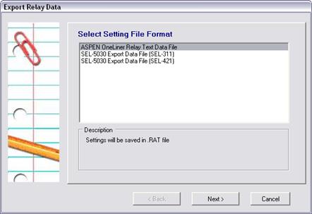
Relay data can be exported to these data file formats:
• ASPEN OneLiner relay text data file (.RAT).
• SEL-5030 Export Data File (SEL-311). This option is available for most relays.
• SEL-5030 Export Data File (SEL-421). This option is available for overcurrent relays only. It will be available for other relays at a later time.
TO TAKE RELAYS, FUSES OR RECLOSERS IN OR OUT OF SERVICE:
1. Select one or more devices in the relay group and press On/Off Line.
The status of the selected devices will toggle from on-line to off-line, or vice versa. The device list will be updated with the on-line devices listed first.
TO VIEW AND EDIT LOGIC SCHEMES AND COORDINATING PAIRS:
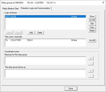
1. Press the Protection Logic tab to manage the logic schemes and coordination pairs for this relay group.
The top list box of the Protection Logic page shows all the logic schemes. The other two list boxes below are for coordinating pairs that involve this relay group.
TO VIEW LOGIC SCHEME DATA:
1. In the top list box, double-click on a scheme.
A dialog box will appear to show you the parameters of the logic scheme.
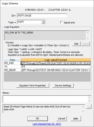
Please refer to SECTION 6 LOGIC SCHEMES for more information on the protection-scheme parameters.
TO ADD A LOGIC SCHEME:
1. Click on "+" within the Logic Schemes group box.
The Logic Scheme Window will appear to let you configure a new scheme. Please see 6.1 LOGIC SCHEMES for more information on how to create a logic scheme.
TO CHANGE THE ON-LINE/OFF-LINE STATUS OF A LOGIC SCHEME:
1. In the top list box, select a scheme. Press On/Of to toggle the scheme’s status between on-line and off-line.
TO DELETE A LOGIC SCHEME:
1. In the top list box, select a logic scheme. Press "-" to delete it.
TO CHANGE THE ON-LINE/OFF-LINE STATUS OF A LOGIC SCHEME’S PILOT-COMMUNICATION CHANNEL:
1. In the list box labeled Pilot comm. channels, select the entry you want to change and Press On/Off button to toggle the channel status between on-line and off-line.
The “Pilot comm. channels.” list box shows the list of all the remote bus names where the relays referenced by elements of the logic schemes in this relay group are located. For example, the Pilot Comm. Channels list in the relay group “6 NEVADA 132.kV – 2 CLAYTOR 132.kV 1L” dialog box in the picture above includes the entry “To: 2 CLAYTOR 132.kV” because the logic equation of the scheme POTT-24155 in this relay group contains the RO_FAR element, which references the [ZP3 Pickup] of the phase distance relay CLPhase2 at the bus CLAYTOR 132.kV.
When evaluating the logic equations, OneLiner will always treats all elements associated with off-line comm. channel as Not Assert (False) regardless of the operating status of the relays referenced by these elements (e.g. CLPhase2 in the above example).
TO DISPLAY A LOGIC SCHEME:
1. In the top list box, select a logic scheme. Press Show to display the Logic Scheme Window.
TO ADD A COORDINATING PAIR:
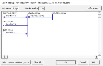
1. Click on "+" within the ‘Backups for this relay group’ group box to add a coordinating pair where the current relay group will be the primary relay.
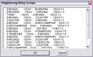
A dialog box will appear to let you select the backup relay group(s). The dialog box can display the neighboring groups as graphically as shown in the following picture:
Or in some part of a complex network, the dialog box can display a list of neighboring relay groups as shown in the following picture:
2. Click on an entry to select a relay group. Press OK.
The backup relay group will appear in the ‘Backups for this relay group’ list box.
Follow similar instructions to create a coordination pair where the current relay group will be the backup relay. Please refer to the Relay | FORM COORDINATION PAIR COMMAND for an alternative method for creating coordinating pairs.
TO DELETE A COORDINATING PAIR:
1. Select an entry in the ‘Backups for this relay group’ group box or the ‘This relay backs up’ group box.
2. Click on "-" button to the right to delete the coordinating pair.
The select entry will disappear.
TO VIEW AND EDIT EXTERNAL DATA LINK:
1. Press the External Data Link tab to manage the links to the external Relays for this relay group.
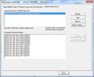
The Linked Device(s) in ASPEN Relay DB list box shows the list of all relay records in the ASPEN Relay Database that are linked to relays in this OneLiner network. The Connected OneLiner Relays list box displays the list of all the relays in this relay group that are linked to the above Relay Database records.
TO REFRESH THE LINKED DEVICE:
1. Select Refresh button and select Yes in from the confirmation dialog to refresh the list of linked device
TO ADD A NEW LINKED DEVICE:
1. Select Add button. If requested, enter the login credential to login to the Relay Database
2. Select location from the database and select a relay in this location to link
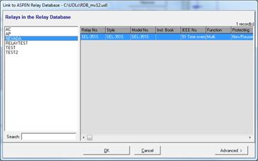
3. Select Advanced button and select a mapping script you want to use to process the settings of the selected Relay Database relay
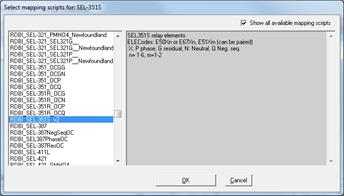
4. Click OK to confirm and close the wizard dialog

5. Select a setting request status and setting group then click on the OK button to start importing settings to relays in this relay group
TO REMOVE A LINKED DEVICE:
1. Select a linked device from the Linked Device(s) in ASPEN Relay DB
2. Click on Remove button to remove this link.
Note: The OneLiner can only remove a linked device item if there is no relay in this relay group is linked to this record.
TO RETRIEVE SETTING:
1. Select a linked device from the Linked Device(s) in ASPEN Relay DB
2. Select “Retrieve Settings…’ button
3. Select a setting request status and setting group then click on the OK button to start retrieveing settings from this external device to relays in this relay group
Main Window
RELAY MENU