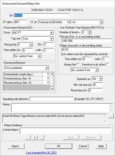

Here are the instructions to enter data for a new ground relay:
1. Enter the basic data.
ID: Enter a name with up to 24 characters for the relay. We recommend that you include in the ID certain mnemonics that identifies the relay type. For example, you may want to end the ID with the letter 'G' for ground relays, and 'P' for phase relays. The ID only has to be unique among fuses and overcurrent relays in the same relay group.
CT ratio: The CT ratio is defined to be the primary/secondary turns ratio of the current transformer. You can either a number value or a ratio in the form of xxx/yyy or xxx:yyy. For example, for a 600A-to-5A CT, enter one of the following 120, 600/5 or 600:5.
CT at: Select the desired location of the current sensor from the dropdown box. The CT Location list box contains a list of the possible current sensor locations for transformers. The relay can sense either the terminal current, or the current flowing in the primary or secondary neutral. In the case of an autotransformer, the program will correctly sense the common neutral current (select either of the Auto Neutral items). For a 2-winding transformer with a delta winding, or a 3-winding transformer with a delta tertiary, you can place the current sensor within the delta where the circulating current is measured.
NOTE: The CT inside 2-winding transformer delta option is available only in version 15.6 or later.
NOTE: Ignore this step for transmission lines and phase shifters because their relays are always assumed to sense the terminal current.
Operates on: Select the relay operating quantities: 3Io, 3I2, Io or I2. Io and I2 are the zero- and negative-sequence current, respectively. For a relay on the tertiary winding of a 3-winding transformer, select ‘Io’ if there is only one CT, and ‘3Io’ if there are three CTs.
Min. trip time: The fastest time in seconds that the relay can trip.
The reset time: This is the time required for the ‘disk’ to rotate back to the original position, after a full travel at time dial 10. The program uses this datum to check the coordination between relays and reclosers.
Memo: The memo is for any notes you wish to keep for this relay. It can have up to 512 characters. Quote character is not allowed in the note.
Click on the … button near the upper right corner of the text area below the Memo field to open the Supplemental Object Properties dialog box with a data grid to enter data for the following data fields:
In/Out of service date: Click on the … button and enter the desired dates. See the Details and Techniques section “In/Out of service and tags” for more information.
Asset ID: An identifier for facilitating data exchange with external databases. The asset ID can have up to 127 characters.
Tags: Enter list of tag strings separated by semicolon. The tags are for organizing objects that are related for some purpose. Please see documentation for Network | Apply Tag for more information.
User-defined fields: These are custom data fields that are defined by the user. Please see documentation for File | Preferences for information about how to specify the template for these data fields.
2. Enter parameters for the time element.
Curve: Click on the dropdown box entry ‘Select from library’. The Curve Selector will appear.
Select a curve in the curve library and press ‘Select this curve’. The name of the selected curve will be copied to the Curve edit box.
Note: Detailed instructions on how to use the Curve Selector are available in Section 5.8 CURVE SELECTOR.
For a relay with no time element, select ‘N/A’. You can ignore the rest of the time-element parameters and proceed to step 3.
Tap unit: Click on the 'Tap unit' drop down list box and select a tap unit.
Each tap unit is a collection of discrete pickup values that the relay can accept. The tap units are listed in alphabetical order. The list includes all tap units found in the relay library files.
Select ‘N/A’ if you wish to enter a pickup value directly without referencing a tap unit.
Otherwise select a tap unit in the list.
Pickup: If you selected a continuous tap unit or selected ‘N/A’, enter the pickup in secondary amperes in the ‘Pickup (A)’ edit box.
If you selected a discrete tap unit, either type in the pickup value (in secondary amperes) or select a value in the 'Pickup (A)' drop down list box.
Time dial: Enter a time-dial setting between the minimum and maximum time-dial lever of the selected overcurrent relay in the ‘TD’ edit box. The time dial value should be set to 1.0 if the relay has only curve.
Note: You can use the Time Dial Calculator to calculate the time dial from input values of time delay and multiple of pickup. See APPENDIX C: TIME DIAL CALCULATOR for details.
Time adder (in seconds) and time multiplier for the time element: The time delay is given by T’=aT+b, where ‘T’ is the time given by the unshifted curve, and ‘a’ is the time multiplier and ‘b’ is the time adder.
Directional: Select an appropriate dropdown box entry: 'Dir. Control: Fwd.’, 'Dir. Control: Rev.’ or 'Dir. Control: None’ that matches the directional supervision logic of the time delay element of the relay.
Signal only: Enter the keyword ‘OC’ in the ‘Signaling only elements’ edit box if the time element is part of a logic scheme, and it is not used to trip any circuit breakers directly.
3. Enter parameters for the instantaneous/definite time element.
Number of levels: Enter the number of pickup levels in the edit box. The number of levels must be between 0 and 6.
Pickup levels: Enter the list of pickup values in secondary amperes (List items are separated by commas). The list can have up to 6 values for definite time element level 1 through 5 plus the instantaneous pickup. The pickup values must be sorted in ascending order.
Delays: Enter the list of definite time delays in seconds, and/or zero delay for the instantaneous element, that correspond to the pickup levels above (List items are be separated by commas). The delay values must be sorted in descending order.
Always flat: When this option is marked, the definite time segment is flat for currents above the ‘Pri. A’ setting. Otherwise, the program will compute the time delay as the smaller of the two values: the definite time value, and the time delay of the curve.


“Always flat” off. “Always flat” on.
Directional: Select an appropriate dropdown box entry: 'Dir. Control: Fwd.’, 'Dir. Control: Rev.’ or 'Dir. Control: None’ that matches the directional supervision logic of the instantaneous/definite time element of the relay.
Sensitive to dc offset: Mark this check box if the relay’s instantaneous unit does not filter the dc offset and is affected by it.
The program uses this datum when checking the settings of the overcurrent instantaneous units.
Time adder (in seconds) and time multiplier for the definite time element: The time delay is given by T’=aT+b, where ‘T’ is the time given by the unshifted curve, and ‘a’ is the time multiplier and ‘b’ is the time adder.
Signal only: Enter the keyword ‘INST’ or ‘DTx’, x=1-5, in the ‘Signaling only elements’ edit box if the corresponding element(s) are part of a logic scheme, and it is not used to trip any circuit breakers directly.
4. Enter the parameters of the directional element: If the time element and/or the instantaneous/definite time element are directional, select the direction element type and enter it parameters in the grid control.
4a. Vo,Io or V2,I2 polarized directional element:
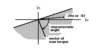
Char. angle: The characteristic angle, in degrees, is the angle between the polarizing vector (–3Vo or –V2) and the vector of maximum torque. The vector of maximum torque defines a half plane, which is shown shaded in the following figure. A forward direction is declared in Vo,Io polarized relay whenever Io lies within the shaded region, and in negative-sequence polarized relay whenever I2 lies within the shaded region. The characteristic angle is initialized to -90 degrees.

Forward pickup: Enter the element pickup value (3Io or 3I2) in forward direction in secondary amperes.
Reverse pickup: Enter the element pickup value (3Io or 3I2) in reverse direction in secondary amperes.
4b. SEL negative-sequence voltage-polarized directional element: Enter the following setting parameters for this element:
Z2F Forward directional Z2 threshold (secondary ohm)
50QF Forward directional overcurrent pickup (secondary A)
Z2R Reverse directional Z2 threshold (secondary ohm)
50QR Reverse directional overcurrent pickup (secondary A)
a2 Positive sequence restrain factor I2/I1
k2 Zero sequence restrain factor I2/I0
Z1ANG Line positive sequence impedance angle (degrees)
PTR PT ratio
NOTE: For details of relay element setting and logic, refer to SEL-421-4,-5 relay reference manual.
4c. SEL zero-sequence voltage-polarized directional element (32V): Enter the following setting parameters for this element:
Z0F Forward directional Z0 threshold (secondary ohm)
50QF Forward directional overcurrent pickup (secondary A)
Z0R Reverse directional Z0 threshold (secondary ohm)
50GR Reverse directional overcurrent pickup (secondary A)
a0 Positive sequence restrain factor I0/I1
Z0ANG Line zero sequence impedance angle (degrees)
PTR PT ratio
Note: For details of relay element setting and logic, refer to SEL-421-4,-5 relay reference manual.
IMPORT SETTING FROM MANUFACTURER RELAY SETTING FILE OR RELAY DATABASE:
11. Press the Import button
See instructions in Section 3.2 RELAY GROUP xe "Properties:relay group"PROPERTIES COMMAND.
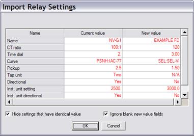
When import is complete, a dialog box will appear showing existing and new value of relay parameters:

Press OK to apply the new settings to the Overcurrent Ground Relay dialog box.
Note: The Import button is not available if the relay is already linked to a setting file on disk or to a data record in the ASPEN Relay database.
LINK TO ASPEN RELAY DATABASE:
12. See instructions in Section 5.9 LINK TO ASPEN RELAY DATABASE .
See, also, APPENDIX G: EXTERNAL RELAY SETTING DATA for a more detailed discussion on the linkage to the Relay Database.
TO CLOSE THE OVERCURRENT RELAY DIALOG BOX:
13. Press OK to close the Overcurrent Ground Relay dialog box.