 on the Device Palette. The cursor
will become a cross with a transformer symbol attached to it.
on the Device Palette. The cursor
will become a cross with a transformer symbol attached to it.The New | 3-Winding Transformer command in the Main Window lets you add a new 3-winding transformer among three buses.
TO ADD A NEW 3-WINDING TRANSFORMER FROM THE DEVICE PALETTE:
1a. Select New 3-Winding Transformer on the Device Palette
Click on the 3-winding transformer button  on the Device Palette. The cursor
will become a cross with a transformer symbol attached to it.
2a. Drag-and-Drop the new transformer
Click the left mouse button on the one-line diagram where you want to place the first end of the new transformer. With the mouse button held down, move the cursor toward the spot where you want to place the second end. A new 3-winding transformer symbol will appear with its far end moving with the cursor. The transformer’s third terminal will be shown connected to a new bus.
Note: Clicking on an existing bus will attach the first end of the new transformer to the bus. Clicking on end segment of an existing branch will place the new transformer in series with that branch.
Release the mouse button where you want to place the second terminal. A dialog box will appear asking you for the transformer data.
Note: When you move the transformer’s far end over an existing bus, the bus symbol will be highlighted in red. You can release the mouse button to attach the second end of the transformer to that bus.
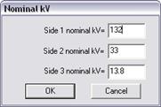
Enter the nominal kV for the new transformer’s terminals when one or more terminals are not connected to an existing bus.

Note: If you place the second end of the transformer too close to the first one, the program will ignore the command.
After completing data input for the new transformer, you can connect its terminal to any existing node having the same kV using the Merge Bus command.
TO ADD A NEW 3-WINDING TRANSFORMER USING MENU COMMAND:
1b. Select the three terminal buses.
Click the left mouse button once on the first terminal bus. Then, with the <Shift> key held down, click the left mouse button once on the second bus and once on the third bus.
Note: The third bus you click on should always be the tertiary bus. The order in which you click on the first two buses is important only if you are making a wye-delta connection. In that case, the bus that is connected to the wye winding must be selected first.
The three bus symbols will turn dotted red when selected.
2b. Select the Network | New | 3-W Transformer command.
A dialog box will appear asking you for the parameters of the new 3-winding transformer.
3. Input the transformer identifiers.
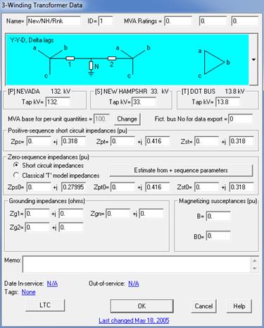
The transformer’s terminal buses are listed at the top of the dialog box. The first bus listed will be referred to as, from left to right, Bus1, Bus2 and Bus3. Bus3 is also referred to as the “tertiary”.

Ckt ID: A two-character circuit identifier that is most commonly used to distinguish between parallel transformers. The circuit ID can also be used to mark the transformer as a fictitious transformer generated by network equivalence. Refer to the COLOR | SPECIAL COLOR CODE COMMAND for further discussion.
Note: Two 3-winding transformers are considered to be “in parallel” when their primary and secondary buses are the same.
Name: A 16-character name for the transformer.
4. Select a winding configuration.
The following nine winding configurations are shown graphically in the drop-down list box.
1. Wye-wye-wye
2. Auto-wye-wye
3. Wye-wye-delta, delta lags
4. Wye-wye-delta, delta leads
5. Auto-wye-delta, delta lags
6. Auto-wye-delta, delta leads
7. Wye-delta-delta, delta lags
8. Wye-delta-delta, delta leads
9. Delta-delta-delta
10. Zigzag-zigzag wye, wye leads.
11. Zigzag-zigzag wye, wye lags
Select a winding configuration by scrolling through the selections in the graphical drop-down list box and choose one by clicking the left mouse button once on the picture.
Note: OneLiner also supports these two configurations:
•Zigzag-wye-delta with wye leads.
•Zigzag-wye-delta with wye lags.
In both cases, the delta winding is assumed to be inside the tank and has no external connection. Instructions on how to create these two transformer types can be found in section 4.7.
5. Input the transformer parameters.
MVA1, MVA2, MVA3: MVA ratings of the transformer. The Power Flow Program checks for overloads using these MVA ratings. Also one of these rating could be reserved for PRC-023 checking.
Tap kV: The transformer tap kV at the three bus terminals.
MVA Base: MVA base for all per-unit quantities. You can enter the MVA base of the transformer directly in the edit box if the transformer object is new. To change the MVA base of an existing transformer, you must first press the “Change” button. A dialog box will ask you for the new MVA base:

Fict. bus no. for data export: When you convert the network data to PTI PSS/E (Version 26 or prior), GE, and ANAFAS format, the conversion logic will assign this bus number to the middle bus of the T-equivalent.
Zps, Zpt, Zst: Positive-sequence short-circuit impedances in per unit (based on the transformer’s base MVA and the tap voltages).
Estimate from + Seq. Impedances: For a wye-wye-delta transformer, press this button to get a set of zero-sequence impedances that are computed based on the positive-sequence parameters Zps, Zpt and Zst. It is important to stress that for Zps, the impedances measured in the positive-sequence short-circuit test is usually not equal to the impedance measured in the zero-sequence short circuit test. We recommend that you use this method to get the zero-sequence impedances when there is no zero-sequence test information available.
Zps0, Zpt0, Zst0: Zero-sequence short-circuit
impedances in per unit (based on the transformer’s base MVA and the tap
voltages).
NOTE: In IEEE 57.12.90 standard transformer test reports,
Zps0, Zpt0, Zst0 impedance values are labeled Z1Ns, Z1No and Z2No
respectively.
For wye-wye-delta transformers, you can alternatively enter the T-model impedances in per unit (based on the transformer’s base MVA and the tap voltages). Click on the radio button Classical T-Model Impedances and enter the following:
Zpm0, Zsm0, Zmg0: Impedance of the T model in per unit (based on the transformer’s base MVA and the tap voltages). Zpmo is the impedance between Bus1 and the middle bus, Zsm0 is the impedance between Bus2 and the middle bus, and Zmg0 is the impedance between the middle bus and ground.
B, B0: Positive- and zero-sequence magnetizing susceptances in per unit (based on the transformer’s base MVA and the tap voltages). For the zigzag-zigzag-wye transformer, this susceptance is assumed to be that of the wye winding.
Zg1, Zg2, Zg3, Zgn: Grounding impedances in ohms (Should be entered without any multiplication by 3). Some of these edit boxes may be hidden.
Note: See Sections 4.5 TRANSFORMERS - GENERAL INFORMATION and 4.7 3-WINDING TRANSFORMERS for a discussion of the transformer model .
6. Enter a memo.
The memo is for any notes you wish to keep for this transformer. It can have up to 512 characters.
Click on the … button near the upper right corner of the text area below the Memo field to open the Supplemental Object Properties dialog box with a data grid to enter data for the following data fields:
7. In/Out of service date: Click on the … button and enter the desired dates. See the Details and Techniques section “In/Out of service and tags” for more information.
8. Tags: Enter list of tag strings separated by semicolon. The tags are for organizing objects that are related for some purpose. Please see documentation for Network | Apply Tag for more information.
9. User-defined fields: These are custom data fields that are defined by the user. Please see documentation for File | Preferences for information about how to specify the template for these data fields.
TO SPECIFY THE LOAD TAP CHANGER PARAMETERS:
1. Click on the "LTC” button.
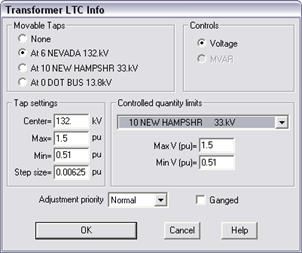
A dialog box will appear asking you for the load tap changer (LTC) parameters.

Note: The LTC is for Power Flow users only. The parameters here have no effect on short circuit simulations.
2. Select the location of movable taps. Click on:
None: If the transformer does not have movable taps.
At Bus1: If the movable tap is on the Bus1 terminal side.
At Bus2: If the movable tap is on the Bus2 terminal side.
At Bus3: If the movable tap is on the Bus3 terminal side.
3. Specify the LTC tap settings.
Center: Center tap position in kV. This is the neutral position of the LTC tap. The default is the nominal kV.
Max and Min: Maximum and minimum tap in per unit based on the center-tap kV.
Step size: Step size in per unit based on the center-tap kV. Enter zero if continuous.
4. The "Voltage" radio button in the 'Controls' box is automatically selected.
5. Click on the "at" drop down list box and select the controlled bus.
The program will move the tap to regulate the voltage magnitude of the controlled bus.
6. Specify the controlled quantity limits.
Controlled bus: Select controlled bus from the dropdown list.
Max and min V (pu): Maximum and minimum controlled bus voltage magnitude in per unit.
These values (plus/minus a tolerance of 0.003pu) define the upper and lower limits for the Power Flow program to control the bus voltage level.
7. Select an adjustment priority.
Leave this setting to ‘normal’ except when this LTC belongs to a group of tightly coupled LTCs that must be adjusted in a certain order. For example, when adjusting LTCs in a radial network, the LTCs closest to the source need to be adjusted first before those downstream.
Assign ‘High’, ‘Medium’ and ‘Normal’ priority to this LTC according to the order this LTC needs to be adjusted relative to other closely coupled LTCs in the vicinity.
Within a power-flow iteration, the high-priority LTCs are adjusted first. The program then recalculates the bus voltages before adjusting the medium-priority LTCs, and so on.
8. Mark the ‘Ganged’ button if this LTC is moving its tap in locked step with one or more LTCs that control the same bus voltage.
Note: The ganged LTCs must have the same adjustment priority, same voltage range, and same range of tap movement.
9. Press OK to close the LTC properties dialog box.
TO CLOSE THE TRANSFORMER DIALOG BOX:
1. Press OK to close the transformer properties dialog box.
A new 3-winding transformer symbol will be shown. The program adds a diagonal slash to the symbol when the LTC is active.
Main Window
NETWORK MENU