OneLiner offers a wide variety of 2- and 3-winding transformer models, including auto-transformers and transformers with complicated neutral connections. The transformer models in OneLiner are based on the paper:
V. Brandwajn, H.W. Dommel and I.I. Dommel, "Matrix Representation of Three-Phase N-Winding Transformers for Steady State and Transient Studies," IEEE Trans. on PAS, June 1982.
The same method is used in the Electromagnetic Transients Program (EMTP) for modeling multi-phase transformers.
The input data for each transformer consist of its physical parameters that can be obtained readily from the manufacturer's data sheets or from parameters of existing short-circuit models. The equivalent circuits for the transformers are formulated by the program, and never by the user. This approach enables OneLiner to:
• Model the plus or minus 30 degree shift in wye-delta transformers;
• Represent complicated transformer types exactly;
• Avoid the use of fictitious buses;
•Output explicitly, in amps, the neutral current for each auto-transformer and the tertiary circulating current for each 3-winding transformer.
Some general features of the transformer models are described in the following sections.
Impedances of 2-Winding Transformers
Each 2-winding transformer has two terminal buses: Bus1 and Bus2. The short-circuit impedance of the transformer, Zps, is measured in a short circuit test in which the Bus1 terminal is excited while the Bus2 terminal is shorted to ground. In the case of a wye-delta transformer, the Bus1 terminal is assumed to be connected to the wye winding. (Otherwise, it is not possible to measure a finite zero-sequence short-circuit impedance.) The positive- and zero-sequence impedances are always the same for a transformer that is made up of separate, single-phase units.
The short-circuit impedances are in per-unit based on the transformer’s base MVA and the tap kVs.
The use of the tap kVs, instead of the nominal kVs, as the voltage base of the per-unit impedance is a departure from most of the commercial short circuit programs. The main reason we chose to use the tap kVs as the voltage base is the ease of entering the short-circuit impedance: The user can copy the per-unit test impedance from the transformer’s data sheet directly into the program without any modification. This is possible even when the tap kVs are not the same as the nominal kVs.
In the case when the actual tap kVs do not match the tap kVs when the transformer was tested, we recommend that the user enter the per-unit impedance of the closest set of Bus1-Bus2 taps – again, without any modification.
Impedances of 3-Winding Transformers
Each 3-winding transformer has three terminal buses: Bus1, Bus2 and the tertiary bus. The three short-circuit impedances of a 3-winding transformer are defined as follows:
Zps: Impedance measured at the Bus1 terminal with the Bus2 terminal shorted to ground and the tertiary open-circuited.
Zpt: Impedance measured at the Bus1 terminal with the tertiary shorted to ground and the Bus2 terminal open-circuited.
Zst: Impedance measured at the Bus2 terminal with the tertiary shorted to ground and the Bus1 terminal open-circuited.
For wye-wye-delta transformers, you have the option of entering the zero-sequence short-circuit impedances Zpso, Zpto and Zsto, or the impedances of the classical T model. If you decide to enter the short-circuit impedances, please note that Zpso should be smaller than Zps.
Similar to 2-winding transformers, the impedances of a 3-winding transformer are in per-unit based on the transformer’s base MVA and the tap kVs (and not the nominal kVs).
Tap Voltages
The tap voltages of the transformer windings affect the turns ratio of the transformer as well as the short-circuit impedance values. (See the last paragraph under "Short Circuit Impedances".) The transformer terminals are assumed to be connected to the same physical winding taps in the short-circuit test as in actual use. The tap voltages you specify must be in kV, line-to-line.
Magnetizing Impedance
The magnetizing impedance of a transformer is the apparent impedance measured at a terminal with the other terminals open-circuited. The magnetizing impedance of most transformers is very large (>50 per unit) in all sequences and can be ignored in short circuit studies.
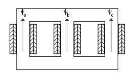
The zero-sequence magnetizing impedance of three-leg-core transformers is a notable exception. In some cases it is as low as 1.0 per unit. The low impedance is a direct result of the 3-leg-core construction. When a set of 3-phase windings is excited by zero-sequence current, the three fluxes are forced out of the iron core to return through the air or oil where the magnetic permeability is much smaller than that of iron. The low permeability in the flux path results in low apparent impedance of the windings.

Figure 4.5: A three-leg-core transformer. This figure shows the fluxes produced by zero-sequence current.