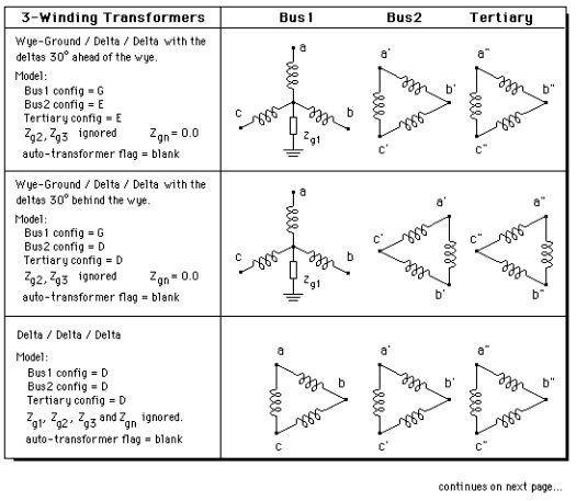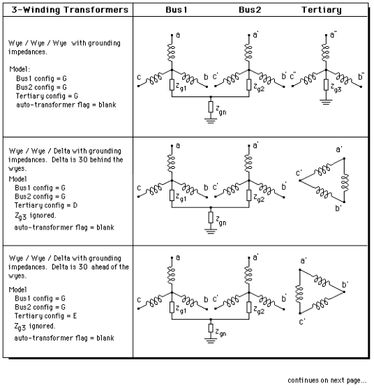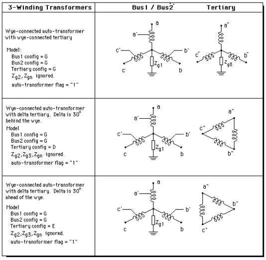
The program offers a variety of 3-winding transformer models. The basic configurations available are shown in Figure 4.8.
Again, a number of variations can be derived from these basic configurations by varying the grounding impedances. See Figure 4.7 for examples on how this can be done for the basic configuration where the first two windings are wye-connected.
The parameters in the first column -- namely “Bus1 config”, “Bus2 config”, “Tertiary config”, and “auto-transformer flag” -- are set by the program. Users need not enter these parameters explicitly.

Figure 4.8: Basic three-winding transformer configurations in use. The 'in use' configurations must be one of the configurations shown in this figure.

Figure 4.8 (continued): Basic three-winding transformer configurations in use. Numerous variations can be derived from the three basic forms on this page. See Figure 4.7.

Figure 4.8 (continued): Basic three-winding transformer configurations in use.
In addition to the above configurations, OneLiner supports the following 3-winding transformers:
•Zigzag-zigzag-wye with wye leads
•Zigzag-zigzag-wye with wye lags
The config parameter is set to ‘Z’ for a zigzag winding. The configuration parameter ‘G’ is used when wye winding leads, and to ‘X’ when wye winding lags.
OneLiner also supports the configurations:
•Zigzag-wye-delta with wye leads.
•Zigzag-wye-delta with wye lags.
In both cases, the delta winding inside the tank and has no external connection. This is how you can create these two types of transformer:
1. First create a two winding transformer with zigzag-wye configuration (with wye either leading or lagging).
2. In the 2-wnding transformer dialog box, enter a negative value for the zero-sequence magnetizing susceptance B0, which represents the leakage impedance between the wye winding and the delta winding.
OneLiner will automatically draw the three winding symbols on the one-line diagram, next to the transformer.