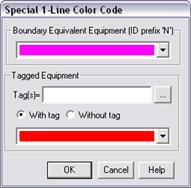
The Color | Special Color Code command in the Main Window allows you to assign special colors to identify (1) fictitious branches and generators created by boundary equivalence, and (2) network equipment with certain tags. These special colors override the colors that would have been assigned on the basis of the equipment's nominal kV.
The colors you assign in this command, including the color ‘white’ (which makes the equipment invisible), have no effect on the network model.
TO ASSIGN SPECIAL COLORS:
1. Select the Diagram | Color | Special Color Code command.
A dialog box will appear.

3. Select a special color for fictitious branches and generators.
The boundary-equivalent algorithm creates fictitious branches and fictitious generators at the boundary of the retained network. The fictitious elements are given a special ID, which is shown at the caption of the top group box. The fictitious branches and generators are drawn on the one-line diagram with a different color, which you can specify here.
Note: You can change the ID for fictitious branches and generators within the Network tab of the File | Preferences dialog box.
Use the drop-down combo box in the top group box to select a color.
4. Select a special color for network elements with certain tags.
Press the button labeled “…” to select one or more tags.
If you selected more than one tag, then the special color is used only if the network element has all of the selected tags.
Click on the radio buttons “With tag” and “Without tag”, depending on whether you want to assign the special color to network elements with the tags, or without the tags you specified.
Use the drop-down combo box in the bottom group box to select a color.
5. Press OK.
The one-line diagram will be redrawn with the new color.
Main Window
DIAGRAM MENU