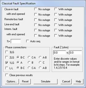
The Specify Classical Fault command in the Main Window lets you specify and simulate one or more classical faults. To activate this command you must first select either (1) a relay group if you wish to simulate a close-in fault, an intermediate fault, or a line-end fault, or (2) a relay group or a branch if you wish to simulate an intermediate or a line-end fault, or (3) a bus if you wish to simulate a bus fault. These three methods are explained in turn.
TO SPECIFY CLOSE-IN, INTERMEDIATE OR LINE-END FAULTS BY SELECTING A RELAY GROUP:
1. Select a relay group.
Click the left mouse button once on a relay group.
The relay group symbol will turn dotted red when selected.
2. Select the Faults | Specify Classical Fault command.
A dialog box will appear asking you to specify the faults to be simulated. The initial selections are those of the last fault simulation.

3. Clear fault options (optional)
Press Clear to remove the check marks from all the fault simulation options and to reset the fault impedance to zero.
4. Select the fault types.
Click on check boxes labeled "No outage" and "With outage" to select one or more of the following fault types. "No outage" means no branch outage will accompany the fault. "With outage" means one or more branch outages will be taken when the fault is applied. In the case of "with outages" another dialog box will appear later to let you specify the branches to be outaged.
Close-in fault: A fault immediately in front of the selected relay group.
Close-in fault with end opened: A fault immediately in front of the selected relay group with the remote end of the branch disconnected. If the branch is a transmission line with intermediate tap buses, the far end of the first segment will be disconnected.
Remote-bus fault: A bus fault at the far end of the branch. If the branch is a transmission line with intermediate tap buses, the remote-bus fault will be applied to the "real bus" at the opposite end.
Line-end fault: A fault at the far end of the branch with the far end of the branch disconnected. If the branch is a transmission line with intermediate tap buses, the line end fault will be applied to the last segment of the line.
Intermediate fault (also called a sliding fault): A fault in the middle of a transmission line. The location of the fault is specified in the next step. This option is not available to relay groups on switches, transformers or phase shifters.
Intermediate fault with end opened: A fault in the middle of a transmission line with the far end of the line disconnected. (On a line with intermediate tap buses the "far end" refers to the end of the entire line.) The location of the fault is specified in the next step. This option is not available to relay groups on switches, transformers or phase shifters.
Note: In simulating close-in fault with end opened, remote bus fault, line-end fault or any of the intermediate fault on a line with multiple sections, the program will automatically trace the network topology to the true end of the line to apply the fault accordingly. See Section 8.9 for techniques for managing lines with multiple sections.
5. If you selected any of the intermediate faults, you must specify the location of the faults.
To simulate an intermediate fault on a single position on the line, enter the location of the fault as a percentage of the line’s positive sequence impedance between the near-end and far-end buses.
Intermediate faults must have a location percentage in the range 0.01 to 99.99. Zero percent is defined to be at the selected relay group, or at the near-end bus of the line. One hundred percent is defined to be at the far-end bus. If the line has intermediate tap buses, the percentage is for the entire line. Section 8.9 WORKING WITH MULTI-SECTION LINES has additional details about modeling multi-section lines with tap buses.
To simulate multiple intermediate faults on the line, mark "Auto seq." check box. Two additional edit boxes labeled "From" and "To" will appear. Enter the location increment in the edit box labeled '%', and the percentage range in 'From' and 'To'.
The percentage you specify will be for the whole line. The first intermediate fault will occur at the minimum allowed percentage of the range with succeeding faults appearing at increments of the line length specified by the percentage in the '%' edit box. For example, if you type in a percentage of 20 and leave the default range of 0.0 to 100.0 undisturbed, OneLiner will simulate four intermediate faults at 20%, 40%, 60% and 80%. (The end points are excluded because the allowed locations must lie between 0.01 and 99.99%). As another example, if you type in a percentage of 10 and specify a range from 4 to 40, OneLiner will automatically simulate four intermediate faults at 4%, 14%, 24% and 34%.
6. Select one or more phase connections. Click on:
3LG: Three phase fault.
2LG: Two phase to ground fault.
1LG: Single phase to ground fault.
L-L: Line to line fault.
Click on radio button to select phase ID for each fault connection.
The connections you select will apply to all the fault options selected.
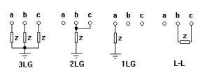
The following figure illustrates the four different phase connections:

7. Specify the fault impedance.
Enter the fault impedance in 'Fault Z (ohm)'. See figure in Step 6 for the position of the fault impedance.
For both the fault resistance and reactance, you have the option of entering multiple values separated by commas, e.g., 0.5, 1, 1,3, 1.5; as a range of values with start, end and number steps, e.g., 5-10:4, which is equivalent to the discrete values of 5.0, 6.25, 7.5, 8.75, and 10.0; or as range of values with start, end and step size, e.g. 1-3@0.5 which is equivalent to the discrete values of 1, 1.5, 2, 2.5 and 3. You can also mix discrete values and ranges.
The number of equivalent discrete values for the fault resistance and the fault reactance must be the same.
Whenever there are multiple values of fault impedances, OneLiner will simulate multiple faults, one for each of the fault impedances.
8. Mark "Clear previous results" to discard all previous fault simulations.
Normally OneLiner appends new simulation result to previous results. You can access any of these results by using the Faults | Show Solution on 1-line, Relay | View Relay Curves, or Faults | Solution Report commands. Over time, OneLiner will accumulate a “stack” of many simulation results. This “Clear previous results” option allows you to clear the stack and start afresh.
9. Change fault-simulation options
Press Options to view the Fault Simulation page of the Preference dialog box. (See documentation of the File | PREFERENCES COMMAND for more information.) Within this page you can change the generator impedance option from subtransient to transient, for example.
10. Press Simulate
If you checked any of the 'With outage' check boxes skip down to step 11.
The dialog box will disappear and OneLiner will begin the fault calculations. A dialog box will appear to inform you of the program's progress.
The Main Window will automatically display the one-line diagram with the post-fault solution. If more than one fault is simulated, the last solution is shown.
11. Select the outaged branches
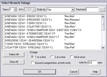
If you marked one or more of the six check boxes labeled 'With outage', a dialog box will appear asking you to specify branch outages.
The outages you specify in this step will apply to all the fault types that have the "With outage" option selected.

The list box contains all the branches within a certain number of buses back from the fault. You can change the extent by varying the “Tiers” parameter at the upper left corner of the dialog box.
In the list box, select the branches to be outaged by marking the check boxes to the left of the branch identifiers.
The following restrictions apply:
1) At most five branches can be taken out of service at once.
2) Whenever you outage a 3-winding, all three terminals of the transformer will be outage all at once.
12. Specify the branch outage options.
Select the branch outage options. Mark one or more of the following check boxes:
1 at a time: To take one branch out of service at a time.
2 at a time: To take two branches out of service at a time. OneLiner will automatically select all possible pairs of branches among those that you selected.
All at once: To take all the selected branches out of service simultaneously.
Ground outaged lines at both ends and enter grounding resistance in ohm: To take a line out of service and ground both ends with the grounding resistance.
13. Press OK to begin fault simulation.
The dialog box will disappear and OneLiner will begin the fault calculations. A dialog box will appear to inform you of the program's progress.
The Main Window will automatically display the one-line diagram with the post-fault solution. If more than one fault is simulated, the last solution is shown. The fault description is shown in the status area near the bottom of the window.
TO SPECIFY INTERMEDIATE OR LINE-END FAULTS BY SELECTING A BRANCH:
1. Select a branch.
Click the left mouse button once on a branch symbol.
The relay group symbol will turn dotted red when selected. The position you clicked on is important: For an intermediate fault, the nearest branch terminal will be defined as 0%. For a line-end fault, the fault will be applied to the opposite end of the branch.
2. Select the Faults | Specify Classical Fault command.
The same fault-specification dialog box will appear. The only difference is that the first four check boxes involving close-in faults will be grayed and disabled.
TO SPECIFY BUS FAULTS:
1. Select a bus.
Click the left mouse button once on the bus symbol.
The bus symbol will turn dotted red when selected.
2. Select the Faults | Specify command.
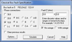
A dialog box will appear asking you to specify the phase connection, fault impedance and outages.

The options in this dialog box are similar to those for the relay-group based method of fault selection and will not be repeated here.
Main Window
FAULTS MENU