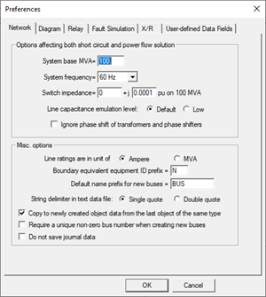
The Preference command in the Main Window lets you view the dialog boxes of six different Options commands within one tabbed dialog box: Network | Options, Diagram | Options, Relay | Options, Fault | Options, Fault | X/R Ratio Parameters and User-defined Data Fields. You can move among these pages by pressing the tabs on top.
The “User defined Data Fields” tab is new in v15.
The program saves the updated parameters only when you press OK. Please be aware that the changes made by this command are not undo-able.
TO CHANGE NETWORK OPTIONS:
On this page you can change modeling settings that affect both short circuit and power flow simulations. Also, on this page, you can control the default values used for new objects and the string delimiters for text data files.
1. Select the Network tab.
The network-options page will appear.

2. Change the system base MVA.
The program will recalculate all the per-unit parameters when press OK.
3. Select system frequency: 50 or 60 Hz.
The program uses the system frequency to convert parameters in cycles to seconds, and vice versa.
4. Change the switch impedance in per-unit.
The program models switches as low-impedance lines. The same impedance is also used to simulate a bypassed series reactor or capacitor.
The impedance value selected must be small to avoid introducing unwanted changes to the network model. However, switches with very small impedance can cause numerical problems and result in incorrect short circuit solutions. The smallest switch impedance one can use is a function of the system being modeled. In most cases, the impedances should be 0.0001 per unit or larger.
If you are changing the system base MVA, the program will automatically adjust this impedance to the new MVA base. You need not change it yourself.
5. Select the level of line capacitance emulation
To emulate the effect of natural line capacitances when no line G+jB is entered, the program automatically adds a very small capacitive shunt at the two ends of the transmission line. The ‘Default’ level is selected empirically to be large enough to avoid mathematical singularity and, at the same time, small enough to have an insignificant effect on short-circuit solutions. However, in ungrounded and weakly grounded systems, the default emulation level may still result in unreasonable X/R ratios in short-circuit simulations. In these cases, the ‘Low’ level is recommended.
6. Mark the check box "Ignore Phase shift" to ignore the phase shifts of wye-delta and zigzag-wye transformers and phase shifters.
This option is put here (instead of under the Faults Simulation tab) because the ignore-phase-shift option will affect both short circuit and power flow simulations.
7. Select a string delimiter.
Character strings in text data files (*.DXT) and relay data file (*.RAT) are enclosed by quotes. You can choose either the single quote or the double quote for that purpose. The single quote was used exclusively prior to version 9. The double quote was added to allow users to have apostrophes in names and comments.
8. Enter an ID prefix for fictitious generators and branches.
The boundary-equivalent algorithm creates fictitious branches and fictitious generators at the boundary of the retained network. The fictitious elements are given a special ID, which you can specify here. The default prefix is ‘N’. This letter is a “prefix” meaning that branches and generators with IDs that begin with letter ‘N’, such as “N1” and “NA”, will be considered fictitious. You can eliminate this ambiguity by entering a 2-letter ID prefix, such as “99”. The fictitious branches and generators are drawn on the one-line diagram with a different color. See documentation for the Diagram | COLOR | SPECIAL COLOR CODE COMMAND for more information.
9. Select default parameters for new objects.
When the “Use the last object’s data as default values” checkbox is marked, the program will automatically use data from the last entered object of the same kind as default values when it displays the data dialog box for new objects. Otherwise, the program will show you a blank info dialog box for new objects.
10. Specify default name prefix for new buses.
The program composes new bus name by automatically appending to this prefix a numeric index that will make the name unique in the network.
Setting the name prefix differently in OneLiner networks to reduce the chance that users will unknowingly create new buses with identical name and nominal kV but are un-related, which will cause incorrect results when these network are compared and/or merged.
11. Select whether bus number is required.
When the “Require a unique non-zero bus number when creating new buses” checkbox is marked, all new buses that you will create in the network will have to be assigned a unique non-zero bus number.
12. Select whether journal data are saved with network data records.
When the “Do not save journal data” checkbox is marked, the program will not store the data record creation date stamp and the user ID in the OLR file. Checking this option will also erase all journal data that may already exist in the file.
Note: The program will always store the “Last changed” date time stamp for all data records regardless of the value of this flag.
13. When done, press another tab or press OK to exit.
TO SPECIFY DIAGRAM OPTIONS FOR THE MAIN WINDOW:
1. Select the Diagram tab.
The diagram-options page will appear.
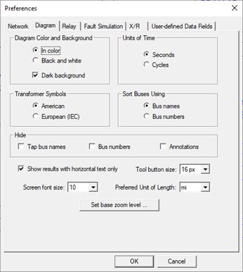
2. Select your color preference. Click on “In color” or “Black & White”.
3. Select the units of time: Seconds or cycles.
Note: For cycles, make sure system frequency is correct in the Network tab.
This selection will affect the textual output of the relay operating times on the one-line diagram.
4. Select either "American" or "European (IEC)" to display either American or European (IEC) transformer symbols.
5. Select sorting preference: by bus name or by bus number.
This option will affect how the program sorts items within dialog boxes, data browsers, and reports.
6. Select whether to hide tap bus names.
Mark "Tap bus names" checkbox to hide the identifier of tap buses. Otherwise, the bus identifier of tap buses will appear on the one-line diagram.
7. Select whether to hide bus numbers.
Mark "Bus numbers" checkbox to not show the bus numbers. Otherwise, the bus number, if not zero, is shown as part of the bus identifier on the one-line diagram.
8. Select whether to hide annotations.
Mark "Annotations" checkbox to not show the annotations on the one-line diagram. Otherwise, the annotations will appear on the one-line diagram.
9. Select whether to always show text horizontal.
Since version 11, the program is capable of showing the text horizontally and vertically. When this option is turned on, all the text will be drawn horizontally as it was done in prior versions of the program.
10. Select the tool button size.
Click on the 'Tool button Size' drop down list box and select the desired size.
Button sizes in pixels of 16 and 24 are available. The new button size will take effect after you will restart the program.
11. Select the screen font size.
Click on the 'Screen Font Size' drop down list box and select the desired font size.
Font sizes 8 to 28 are available. The program will use the selected font size for text in the one-line diagram.
12. Select the unit of length.
Click on the 'Preferred Unit of Length' drop down list box and select the desired unit of length.
Units of length available are: "ft", "kt" (1000 ft), "mi", "m" or "km". Your preferred unit will be used as the default for new transmission lines and as the unit for existing lines of zero length.
13. Set the base zoom level.
Click on the 'Set base zoom level' to use the current diagram zoom as zoom level 1.
You can push the keyboard shortcut key ‘1’ to show the diagram in zoom level 1.
14. When done, press another tab or press OK to exit.
TO SPECIFY RELAY OPTIONS:
On this page you can specify a number of options that pertain to relays.
1. Select the Relay Tab.
The relay options page will appear.
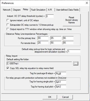
2. Enter the ‘Instant. OC DT delay threshold’ you want to use.
The program will treat OC DT elements with trip delay above this threshold as the Time element, and all the other OC DT elements will be treated as the Instantaneous element.
3. Mark the ‘Ignore instantaneous/DT unit’ checkbox and enter the delay threshold to ignore the instantaneous and DT unit with delay less than the above threshold on all overcurrent relays when (1) plotting the time-current points on the relay curves and (2) calculating the relay operating times.
The program will plot a dotted vertical line for the instantaneous/DT unit in the OC Curves Window, even though it is not used for time-delay calculations.
4. Mark the ‘Extrapolate curves to 1.0 times pickup’ checkbox to use the pickup setting as the starting point of the relay curve.
Most relay manufacturers draw their relay curves with the minimum current at 1.25 or 1.50 times the pickup setting, even though the relays may operate with current smaller than this value. When this “Extrapolate curves” option is selected, the program will extrapolate all relay curves to 1.0 times pickup and will give a finite operating time for any relay current that is higher than the pickup.
5. Mark the Output text report to TTY Window when showing relay operating time on 1-line checkbox if you want the program to produce a table with relay operating time every time relay operating time is displayed on the one-line diagram.
6. Press Reset Stored Library Names to remove library file name reference from relay curves in the current OLR file.
Run this command when the program displays error messages saying certain relay curves cannot be found in specific relay library files. This does not mean that those relay curves could be found in other library files. The reset command will cause the program to scan all the overcurrent relay library files in the Library Directory to search for those relay curves. Once found, the library file name is stored with the rely-curve name in the olr file.
7. Enter the percentages of line impedances you want OneLiner to display when you press the “Line Impedance” button in the distance relay dialog box.
You can specify up to 3 separate percentages for the primary line (the line on which the relay is location) and 3 percentage for the remote lines (lines connected to the far end of the primary lines). When you press the "Line Impedances" button on the distance relay dialog box, the program will show you:
a) The positive- and zero-sequence impedances and the K value for the primary line at locations corresponding to the percentages you specified for the primary line. For example, a percentage of 85 means that OneLiner will show you the line impedances between the relay and at 85% of the primary line. All impedances are in secondary ohms based on the distance relay’s CT and PT ratios.
b) The positive- and zero-sequence impedances and the K value for each of the remote lines, measured from the relay location to remote-line locations that correspond to the percentages you specified. For example, a percentage of 50 means OneLiner will show you the impedance between the relay and the mid-point of each remote line. Note: These impedances do not take into account effects of infeed.
See also, Section 8.9 for techniques for managing lines with multiple sections.
8. Enter default relay pickup time in cycle.
The program uses this “default pickup time” in evaluating operation of logic schemes and in stepped-event analysis..
Note: This value should not be confused with the “Instantaneous delay” setting in the Overcurrent relay dialog box. See 6.1 LOGIC SCHEMES for more details about logic scheme models in OneLiner.
In stepped event analysis, the event time is based on the time at which the circuit breaker opens. We compute this breaker opening time as follows:
FOR PROTECTIVE DEVICES OTHER THAN LOGIC SCHEMES
(1) We first computed the relay's time delay. If that time delay is equal to 0, then it is replaced by the "default relay pickup time". The default relay pickup time is 1 cycle.
(2) We add to that the "interrupting time", which you can change in the relay-group dialog box.
The result is the relay trip time for overcurrent relays, distance relays, voltage relays, differential relays, fuses, and reclosers.
FOR LOGIC SCHEMES
The "default relay pickup time" is incorporated into the processing of logic schemes. To get the breaker-opening time in stepped-event analysis, we add the "interrupting time" to the time delay given by the output of the logic scheme.
9. Specify the default relay setting file folder: When you execute the Relay | Relay Database | Retrieve Setting command and the Retrieve button in the relay dialog boxes, the program will attempt to locate relay setting files that are linked to OneLiner relays in this folder.
10. Mark the Copy SEL relay trip equation to relay memo field checkbox if you want the program to perform this operation when importing data from SEL relay setting files.
11. Specify a tag for Package-B relays. This is used by the Check | Relay Coordination using Stepped Events command. Relays without this tag are considered to be Package-A relays.
12. Specify a tag for relay groups that has a protection scheme with a single pilot that is not modeled in OneLiner. This flag causes the Check | Relay Coordination using Stepped Events command to (1) omit taking double branch outages always, and (2) take single branch outage only if the user wants it.
13. Specify a tag for relay groups that has a protection scheme with a dual pilot that is not modeled in OneLiner. This flag alerts the Check | Relay Coordination using Stepped Events command to look for fast acting backups that may interfere with the pilot scheme.
Single- and double pilot scheme cannot be used for a stub line.
14. When done, press another tab or press OK to exit.
TO SPECIFY FAULT SIMULATION PARAMETERS AND OPTIONS:
On this page you can change the parameters that control how short circuits are simulated. These parameters are stored within the binary data file.
1. Select the Fault Simulation Tab.
The fault simulation options page will appear.
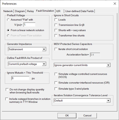
2. Select the prefault voltage profile. Click on:
Assumed “Flat”: To set all prefault bus voltages to a fixed voltage magnitude at an angle of zero degree. Enter the desired prefault voltage magnitude in the edit box below. The default is 1.0 per-unit.
From a linear network solution: To compute the positive-sequence prefault voltages with a linear Ohm’s-Law solution in which each generator is modeled by a voltage source in series with the generator impedance. For each generator, you can specify its open-circuit voltage (magnitude and angle) in the generator info dialog box.
From a Power Flow solution: To use a true power flow solution as the prefault voltage profile. To use this option with a standalone Power Flow Program, you must first solve the power flow within the Power Flow Program and save the case in the OLR file. To use this option with a combined OneLiner/Power Flow executable, the program will automatically prompt you to solve the power flow when you simulate a short circuit.
See section 4.9 for a more detailed discussion on Prefault Voltage Profile and its effect on the fault solution.
3. Specify the “Ignore in Short Circuit” options:
The “ignore” options are designed to help you create a short-circuit case that matches the so-called “classical fault assumptions” in PSS/E and other short circuit programs. Please see the on-line help labeled “Data Conversion” for more information.
Note: The program disregards all the “ignore” options when the prefault voltages are taken from a solved power flow.
Click on "Loads" to ignore all the loads.
Click on "Transmission line G+jB" to ignore the shunt admittances G1, B1, G2, B2, G10, B10, G20, and B20 of transmission lines.
Click on "Shunts with + seq values" to ignore all switched shunts, as well as all the shunt with nonzero positive-sequence admittances G+jB (these are normally capacitors and reactors connected to buses). Zero-sequence shunts, such as zigzag transformers, that have no positive sequence shunt admittance (i.e., B=G=0.0) are not affected by this option.
Click on "Transformer line shunts" to ignore all transformer line shunts. Transformer line shunts are the parameters G1, G2, B1, B2, G10, G20, B10 and B20 in the 2-winding transformer’s info dialog box.
4. Select which generator impedance to use for the positive-sequence model for short circuit studies: subtransient, transient, or synchronous.
5. Select method for simulating MOV protected series capacitors.
Mark the check box Iterate Solution to enable iterative solution of MOV protected capacitor devices.
Enter an acceleration factor to be used in MOV iterative solution. The program applies this factor to update equivalent impedance of MOV-series capacitors between iteration. The factor must be between 0.1 and 1.0.
6. Select definition of fault MVA.
Click on either ‘Current times prefault voltage’ or ‘Current times nominal voltage’ as definition of fault MVA. The first option is the default.
7. Select enforcement of generator current limits.
Select ‘Ignore current limits’ or one of the two generator current limits in the drop-down list box.
The current limits ‘A’ and ‘B’ refer to the two current limits in the generator dialog box.
8. Mark the check box labeled Simulate Voltage-controlled current source to enable the simulation of voltage controlled current sources.
9. Mark the check box labeled Simulate converter-interfaced resources to enable the simulation of converter-interface sources.
10. Mark the check box labeled Simulate type-3 wind plants to enable the simulation of type-3 wind plants.
11. Select desired Iterative Solution Convergence Tolerance Level
•Default: Use OneLiner’s built-in tolerance settings
•Custom: The Iterative Solution Convergence Criteria dialog box will appear to let you specify the following convergence logic parameters:
o Maximum number of iterations
o Voltage and/or current magnitude mismatch tolerance (PU). The base per-unit values are the bus nominal kV and the full load current of the generator.
o Power factor angle deviation tolerance (deg.)
o Relax PF angle deviation tolerance when desire target is not physically attainable.
o
Use memorized phase angle reference
when the device terminal voltage becomes zero due to a fault.
Important note:
manufacturers can implement phase angle reference memory differently. You must
check the manufacturer’s reference memorization methodology and scrutinize the
simulation results when using this option.
12. Enter the mutual coupling impedance threshold in per-unit.
You can direct OneLiner to ignore the mutual coupling between two lines if the 1-norm of the mutual coupling impedance (i.e., |R|+|X| where R+jX is the mutual-coupling impedance) is smaller than this threshold. A threshold of 0.0 – the default – causes all the mutual pairs to be simulated. A very large threshold (e.g., 9999 pu) causes all the mutual pairs to be ignored.
This threshold was implemented to speed up the simulation of intermediate and line-end faults for utilities that have a very large number of mutual-coupling pairs in their network model.
13. Specify whether you want the program to change the display quantities when you browse the results from multiple faults.
By default, the program will show positive-sequence quantities for 3-phase faults, phase-‘b’ quantity for line-to-line faults, and zero-sequence quantities for single-line-to-ground and 2-line-to-ground faults.
Mark the check box if you want the display quantity (phase or sequence quantity or relay operating time) to remain unchanged as you browse a series of fault of different phase connections (3LG, 1LG, L-L, etc.)
14. Specify whether you want the program to show the voltage and current of outaged branches in the solution report.
Due to mutual coupling, zero-sequence current may flow on an outaged line if the ends are grounded.
15. When done, press another tab or press OK to exit.
The new options will take effect next time you simulate a fault.
TO SPECIFY X/R RATIO PARAMETERS AND OPTIONS:
The options and parameters you specify on this X/R page will affect the calculation of ANSI X/R ratios. The computation of ANSI X/R ratios, according to the ANSI/IEEE standard C37.010-1999*, calls for a reactance (X)-only simulation and a resistance (R)-only simulation. The R-only simulation requires a non-zero resistance for each of the network elements. The X-only simulation likewise requires a non-zero reactance for each of the network elements.
During the X-only simulation, when the reactance of a network element is zero, the program substitutes a non-zero value that you can specify in this page. During the R-only simulation, when the resistance of a network element is zero, you can direct the program to substitute a fixed per-unit resistance value, or to compute a resistance based on the typical reactance-to-resistance ratio.
* IEEE Std C37.010-1999, “IEEE Application Guide for AC High-Voltage Circuit Breakers Rated on a Symmetrical Current Basis,” Section 6.3.2 and Annex A, IEEE, Inc., New York, NY, 2000.
1. Select the X/R Tab.
The X/R options page will appear
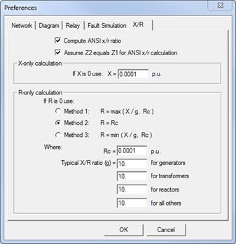
2. Mark the check box “Compute ANSI x/r ratio” if you want OneLiner to compute an ANSI x/r ratio for each fault.
If this check box is not marked, the program will compute the complex x/r ratio, instead of the ANSI x/r ratio. (The complex x/r ratio is computed by dividing the complex part of the total fault impedance by the real part of the total fault impedance.
If you elect to omit the calculation of the ANSI x/r ratio, you can ignore the rest of the options and parameters in this dialog box and proceed to step 6.
Note: When checking breaker ratings using ANSI/IEEE standards, the program will automatically use the ANSI x/r ratio even if this check box is not marked.
3. Mark the checkbox “Assume Z2 equals Z1 for ANSI x/r calculation” to direct OneLiner to assume that the negative-sequence impedance of generators and phase shifters are equal to the positive-sequence impedance, for the purpose of calculating ANSI x/r ratios.
Prior to version 11.7, OneLiner calculated the ANSI x/r ratio with this assumption.
4. Input the reactance to be used in the X-only calculation when the reactance of a network element is zero.
The reactance you enter is in per unit. The default is 0.0001.
5. Specify what resistance to use in the R-only calculation when the resistance of a network element is zero. Select one of three methods:
Method 1 The resistance is computed from the reactance X using a set of typical reactance-to-resistance ratios. The calculated resistance is set to the value Rc if it is too small. Click on Method 1. Then enter Rc, the lower limit for the calculated resistance, and the typical reactance-to-resistance ratios in the four edit boxes near the bottom. The default ratios are 125 for generators, 60 for transformers, and 10 for lines and phase shifters.
Method 2 The resistance is set to a fixed value, Rc. Click on Method 2, then enter Rc in the edit box below. The default value for Rc is 0.0001 per unit.
Method 3 The resistance R is computed based on the reactance X, using a set of typical reactance-to-resistance ratios. The calculated resistance is limited by the value Rc. Click on Method 3. Then enter Rc, the upper limit for the calculated resistance, and the typical reactance-to-resistance ratios in the four edit boxes near the bottom. The default ratios are 125 for generators, 60 for transformers, and 10 for lines and phase shifters.
6. When done, press another tab or press OK to exit.
The new options will take effect next time you simulate a fault.
TO SPECIFY USER-DEFINED DATA FIELDS:
Starting in Version 15, users can define custom text data fields for all the network and relay object types in OneLiner data file to store data for various applications, such as work flow management, data auditing, external database connection, and others. Use the dialog box below to specify the UDF data template, which includes the name and display label for each user-defined field.
The program will use the template to display UDF data in the object properties dialog boxes and in the network data browser for viewing and editing.
UDF data read and write operations are also fully supported in the OneLiner scripting engine.
1. Select the “User-defined Data Fields” Tab:
The User-defined Data Field page will appear
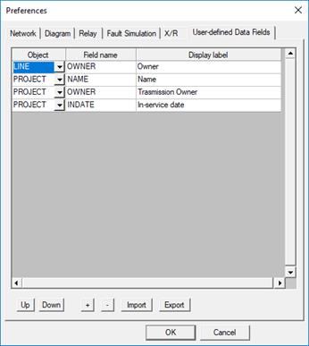
2. Steps to define a new user-defined field
•Click on the ‘+’ button. A new grid row will appear
•Select the object type in the Object column
•Enter the field name. The field name must be unique for the selected object type.
•Enter the field display label.
•Use the Up and Down buttons to set the desired display order of the new field.
3. To delete a user-defined field
Place the cursor
anywhere on the row you want to delete and click on the Delete button 
Note: This action will remove the existing data in this field from all objects of this type in the OneLiner file. There is no Undo for this command.
4. To Export and Import user-defined data fields template
Click on the Export button to save the UDF data template in the grid to a disk file in XML format.
5. Steps to Import user-defined data fields template from file
Click on the Import button to read UDF data template from a disk file in the grid.
Note: This action will remove existing UDF data in the OneLiner file. There is no Undo for this command.
Main Window
FILE MENU