
The following are instructions to enter the data for a new phase distance relay:
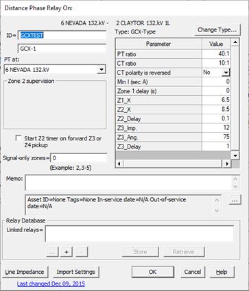
1. Enter the relay ID.
Enter a name with up to 24 characters for the relay. The name only has to be unique among distance relays in the same relay group.
You can enter 12 additional characters in the unlabeled edit box below this one for comments or additional identification information.
2. Press "Change Type” if you wish to change the distance relay-type model being used for this relay.
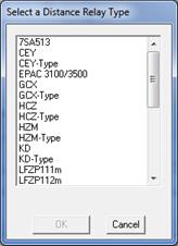
A dialog box with a list of distance relay types will be displayed. Manufacturer-specific relay types are not listed because this “Change Type” feature does not work on them.

Select a distance relay type and press OK.
The 'Relay Type' dialog box will disappear. The program will try to preserve as many as the existing parameters as possible. In some cases, you will need to enter new values. The type name above the data grid will change accordingly.
3. Specify the PT location.
The default location is the bus where the relay group is located. You can alternatively select a neighboring bus by pressing the button labeled ‘…’ within the ‘PT at’ group box.
4. Enable Zone 2 supervision if zone 2 supervises a non-directional overcurrent relay and uses the delay of the overcurrent relay as the zone-2 delay.
Click on the ‘…’ button within the 'Zone 2 supervision' group box to bring up the Curve Selector. Select an overcurrent relay type. Otherwise, leave the setting at '_Fixed' for a fixed zone-2 time delay.
Note: Detailed instructions on how to use the Curve Selector are available in Section 5.8 CURVE SELECTOR.
When you select an overcurrent relay type other than '_Fixed', two additional edit boxes labeled 'Time dial' and ‘Pickup (A)’ will appear. These are the time dial and pickup of the overcurrent relay being supervised by zone 2. The overcurrent relay is assumed to be non-directional.
Enter the time dial value and the pickup setting.
Note: The program will ignore the zone-2 time-delay datum’Z2 delay’ in the data grid. The time delay of zone 2 will be based on the characteristics of the relay curve you select here.
5. Mark the ‘Start Z2 timer on forward Z3 or Z4 pickup’ check box if the zone-2 timer is started when a forward zone-3 or zone-4 picks up.
This is done frequently to speed up fault clearing within a 3-terminal line when logic schemes are not being used. This parameter is used by the stepped-event analysis commands.
6. Enter the zone numbers in the signal-only zones edit box.
A signal-only zone is one that is used exclusively for signaling purposes in a logic scheme. A signal-only zone will not trip the relay directly. Enter a ‘0’ if there is no such zone in this relay. You can use a combination of commas and dashes to indicate a number of zones. For example, “2,3-5” means zone 2, 3, 4 and 5 are signal-only zones.
7. Enter basic setting data within the data grid:
PT ratio: The PT ratio is defined to be the primary/secondary turns ratio of the voltage transformer You can either a numerical value or a ratio in the form of xxx/yyy or xxx:yyy.
CT ratio: The CT ratio is defined to be the primary/secondary turns ratio of the current transformer. You can either a numerical value or a ratio in the form of xxx/yyy or xxx:yyy. For example, for a 600-to-5A CT, enter one of the following 120, 600/5 or 600:5.
CT polarity is reversed: Select Yes if the relay’s CT is wired with a reversed polarity, effectively making it looking backward in the direction of the bus. The program will simulate this connection using a negative value for the CT ratio.
Min I: Fault detector threshold in secondary amperes. One of the phase currents must exceed this value to enable the pickup and tripping of the relay zones. You should enter a non-zero value here to avoid spurious operations.
Z1 Delay: Time delay in seconds when zone-1 trips.
Note: Min I and Z1 Delay may not be available in some manufacturer specific relay types.
8. Input the rest of the relay parameters in the data grid.
The data grid is initially filled with the default values of all the parameters. The meanings of the various relay parameters are explained in the Distance Relay Editor User’s Manual.
10. Enter a memo.
The memo is for any notes you wish to keep for this relay. It can have up to 512 characters.
Click on the … button near the upper right corner of the text area below the Memo field to open the Supplemental Object Properties dialog box with a data grid to enter data for the following data fields:
11. In/Out of service date: Click on the … button and enter the desired dates. See the Details and Techniques section “In/Out of service and tags” for more information.
12. Asset ID: An identifier for facilitating data exchange with external databases. The asset ID can have up to 127 characters.
13. Tags: Enter list of tag strings separated by semicolon. The tags are for organizing objects that are related for some purpose. Please see documentation for Network | Apply Tag for more information.
14. User-defined fields: These are custom data fields that are defined by the user. Please see documentation for File | Preferences for information about how to specify the template for these data fields.
15. Display line impedances.
Press the 'Line Impedance' button.
Note: This button is dimmed and cannot be activated if the relay is not on a transmission line. When relay is on a line with tap bus, the program will automatically trace the network topology to locate the true end of the line. See Section 8.9 for techniques for managing lines with multiple sections.
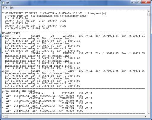
The TTY Window will appear displaying the line impedance in secondary ohms. You can invoke this command any time after the CT and PT ratios have been entered. The report has the following information:
a) The positive- and zero-sequence impedances and the K value for the primary line (the line protected by the relay) at locations corresponding to the percentages you specified for the primary line (in the Relay tab of the File | PREFERENCES COMMAND). For example, a percentage of 85 means that OneLiner will show you the line impedances between the relay and at 85% of the primary line. All impedances are in secondary ohms based on the distance relay’s CT and PT ratios.
b) The positive- and zero-sequence impedances and the K value for each of the remote lines, measured from the relay location to a point on the remote-line, that correspond to the percentages you specified. For example, a percentage of 50 means OneLiner will show you the impedance between the relay and the mid-point of each remote line.
c) The positive- and zero-sequence impedances and the K value for each of the lines that are behind the relay.
A sample report is shown below.

Note: These impedances are results of simple arithmetic operations on the line impedances. None of them is an “apparent impedance”, and none takes into account the effects of infeed.
IMPORT RELAY FROM MANUFACTURER RELAY SETTING FILE:
13. Click on Import button
See details of this step in section 5.2 OVERCURRENT GROUND RELAYS
LINK TO ASPEN RELAY DATABASE:
14. See instructions in Section 5.9 LINK TO ASPEN RELAY DATABASE.
See, also, APPENDIX G: EXTERNAL RELAY SETTING DATA for a more detailed discussion on the linkage to the Relay database.
CLOSE THE DISTANCE PHASE RELAY DIALOG BOX:
15. Press OK to close the 'Distance Phase Relay' dialog box.