The Stepped Event Analysis | Single User-Defined Event command in the Main Window lets you perform a stepped-event analysis with a single initiating event. The initiating event must be a bus fault, a close-in fault or an intermediate fault. The program will simulate subsequent tripping and reclosing events until the fault is cleared or when no further tripping or reclosing events are forthcoming.
Once the program completes the stepped-event simulation, you can play back the events one by one on the one-line diagram.
TO PERFORM A STEPPED-EVENT SIMULATION:
1. Depending on the initiating fault, highlight either a bus, a relay group or a line on the one-line by clicking on its symbol with the right mouse button.
For a bus fault, highlight a bus.
For a close-in fault, highlight a relay group.
For an intermediate fault on a transmission line, highlight either a relay group on the line, or the line itself.
Note: If you highlight the line for an intermediate, the terminal bus that is closest to your mouse click will be considered 0%, and the opposite bus terminal 100%.
2. Select the Faults | Stepped Event Analysis | Single User-Defined Event command.
A dialog box will appear asking you to specify the initiating fault.
IF YOU HIGHLIGHTED A BUS
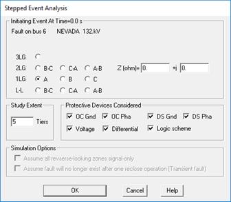
The fault-specification dialog box for the bus fault will look like this.

Click on one of the ten radio buttons to specify the fault type and phase connection.
Enter the fault impedance in ohms.
Enter the study extent in number of tiers from the fault. The program will simulate only the operations of the protective devices that are within this area during the stepped-event simulation. .
Mark the check boxes within the ‘Protective Devices Considered’ group to select the tripping devices you want simulated. Specifically:
Mark ‘OC Grd’ to simulate ground overcurrent relays and ground unit of reclosers.
Mark ‘OC Pha’ to simulate phase overcurrent relays, fuses and phase unit of reclosers.
Mark ‘DS Gnd’ to simulate ground distance relays.
Mark ‘DS Pha’ to simulate phase distance relays.
Mark ‘Logic scheme’ to simulate logic schemes.
Note: The last two check boxes under “Simulation Options” are disabled because these options have not been implemented.
Press OK to commence stepped-event simulation.
IF YOU HIGHLIGHTED A RELAY GROUP ON A TRANFORMER OR PHASE SHIFTER
The fault-specification dialog box is the same as that for the bus fault above.
IF YOU HIGHLIGHTED A RELAY GROUP ON A LINE OR THE LINE SYMBOL
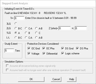
The fault-specification dialog box will allow you apply either a close-in fault or an intermediate fault.

Enter 0 in the percentage edit box to apply a close-in fault.
Enter a percentage between 0.01 and 99.99 to apply an intermediate fault.
The rest of the parameters are the same as those in the bus-fault dialog box above.
3. Viewing the results of a stepped-event simulation.
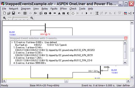
At the conclusion of a stepped-event simulation, the program will display the initiating fault solution on the one-line. In addition, a modeless dialog box will appear to show you a list of all the events. Within the dialog box, the arrow points to the event that is being displayed. The total number of events is shown at the caption of the dialog box.

By default, the program shows you the operating time of all the protective devices and logic schemes within the study area. The operating time of an overcurrent relay in a stepped-event simulation takes into account the following:
1) The accumulation of the disk rotation when currents are detected.
2) Resetting of the disk when currents are interrupted.
3) The breaker interrupting time (you can specify that in the relay-group dialog box).
The program logic also models the tripping and reclosing operations of reclosers.
Press the buttons 0, +, -, A, B, and C on the toolbar if you wish to see the sequence or phase quantities on the one-line diagram.
Press the VCR-like buttons on the toolbar to see subsequent events.
Note: You can move only step forward on the time line. To see a previous event, you must first go back to the first event and then step forward.
Right click the mouse inside the Stepped-Event solution window to select one of the following commands:
•Locate current event on 1-Line: The screen will be centered around the bus where the current event (indicated in the list by the arrow) had occurred.
•Save events as Fault spec file: faults and breaker opens in each event are stored as collection of simultaneous faults. This will allow you to run simulation of each event using command BATCH COMMAND & FAULT SPEC FILE | EXECUTE COMMAND.
•Copy window to clipboard: The content of the stepped-event solution window will be copied to the clipboard as text.
4. Ending a stepped-event analysis.
The program will exit the stepped-event mode when you simulate a fault, modify the network, or perform another analysis, such as voltage-sag or relay coordination checking.
You can terminate the stepped-event mode manually by executing the View | Plain 1-Line command.
The modeless dialog box will disappear when the stepped-event mode ends.
Note: If you close this modeless dialog box by accident, you can open it again with the Faults | Show Fault Solution on 1-Line command.
Main Window
FAULTS MENU