The Set Generator Reference Angle command in the Main Window automatically sets the reference angle of all the generators, with one of the generators being the reference (with angle equal to zero). The reference angle of each generator is set equal to the phase-angle shift of a network path connecting the generator bus to the reference bus. Having a correct reference angle at all the generator is a prerequisite for using the “From a linear network solution” prefault-voltage option for fault simulation. Please refer to Section 4.2 GENERATORS, LOADS,AND SHUNTS for a detailed explanation of the generator model, and to Section 4.9 for an explanation of starting options for fault simulation.
Note: The phase shift angle of all the transformers has to be correct in order for this command to work correctly. We strongly recommend that you run the Check | Network Anomalies command to make sure this is the case.
Note: Fictitious generators that were created by the Boundary Equivalent command can have an internal voltage angle that is not the same as the network-path angle. This command gives you three options on how to do with the internal voltage angle of these fictitious generators.
TO SET GENERATOR REFERENCE ANGLE:
1. Select the Network | Set Generator Ref. Angle command.
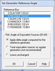
A dialog box will appear to let you select a reference generator whose angle will be set to zero. The reference buses listed in the top list box are actual generators.

2. Select a reference generator by clicking on its bus name with the mouse.
If you selected a reference generator previously, the name of the generator bus will be highlighted in the list box. However, if you have not selected one previously or if the reference generator you selected is no longer active, the program will highlight the first generator bus in the list.
At the conclusion of this command, the reference angle of the generator you selected will be set to zero. In addition, OneLiner will calculate a network-path based angle for every bus in the network. If a bus has a generator, its reference angle will be set equal to network-path based angle of the bus to which it is attached.
3. Select how the reference angle of equivalent sources are updated.
In OneLiner, boundary equivalent sources (“equivalent sources” for short) are modeled as fictitious generator with units with a special unit ID such as ‘N’. The equivalent sources are not real generators. They are there only to compensate for the elimination of some parts of the network. You must select one of the options below to adjust the reference angle of the equivalent sources.
Select “Apply delta angle computed for the reference generator” to use a time-honored method to adjust the internal voltage angle of equivalent sources. This method assumes that the equivalent sources’ internal voltage angle is consistent with the reference generator before this command is executed.
In the dialog box, you can keep the same reference bus or change it to another generator bus in the network; the program logic will adjust the equivalent sources’ internal voltage angle in such a way that the fault solutions will remain unchanged.
Select “Treat equivalent sources as regular generators” to set the internal voltage angle of equivalent sources to the network-path angles, the same way as regular generators. This option is NOT recommended because the reference angle of equivalent sources is rarely the same as the network-path angle.
Select “Unchanged” to leave the reference angles of the equivalent sources unchanged.
4. Press OK to start the command.
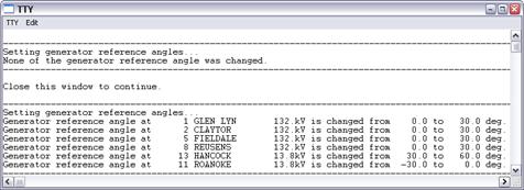
Log of all changes made to generator reference angle will be printed to the TTY window:

5. Select the Menu | Close Window command to close the TTY Window.
Main Window
NETWORK MENU