Each bus can have a generator, a load, a shunt, and a switched shunt. The models for these components are described in the following.
Generators
Each bus can have at most one generator, but each generator can have up to 32 units.
Short Circuit Studies
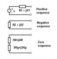
In short circuit simulations, the generator is modeled by a Thevenin equivalent in each sequence network. The equivalent in the positive sequence consists of a voltage source in series with an impedance. There are three different impedances for the positive sequence: the subtransient impedance, the transient impedance and the synchronous impedance. The user can select any one of these three impedances in the Fault Simulation tab of the File | Preferences command. The equivalent in the negative and zero sequences consists of an impedance only. See figure below.,

Figure 4.1: Generator model. R1+jX1 is the positive-sequence impedance. v is the voltage across the internal voltage source. R2+jX2 is the negative-sequence impedance. R0+jX0 is the zero-sequence impedance. Rg+jXg is the impedance between the neutral of the generator and ground.
The internal voltage of the generator, v, is equal to:
• The voltage you specified in the Fault Simulation tab of the File | Preferences dialog box and at 0.0 degree when the Assumed “flat” option is selected.
•The open-circuit voltage and reference angle you specified in the generator’s info dialog box if “From a linear network solution” voltage profile option is selected. See Section 4.9 for details.
•A value based on the power flow solution if starting from a solved case.
Power Flow Studies
A generator bus can be controlling voltage or having fixed MW and MVAR schedule. A voltage-controlling generator can control the voltage magnitude at its local bus terminal or the voltage magnitude at a remote location.
Note: Additional information on current-limited generator models is available in Section 4.10
Loads
Each bus can have at most one load, but each load can have up to 32 units. Each unit has a constant-power, constant-current and constant-impedance component.
Short Circuit Studies
The aggregate load at each bus is modeled as a constant shunt admittance between the bus terminal and ground.
The load admittance, Y (in mhos) is computed from the formula:
Y = f*/(3*v*v)
where f is the load (MW+jMVAR) and v is bus voltage (kV, line-to-ground). The bus voltage, v, is equal to:
• A fixed voltage magnitude (usually 1.0 per-unit) at 0.0 degree if starting from a flat bus voltage profile.
•The calculated voltage if starting from a “from a linear network solution” voltage profile. See section 4.9 for details.
• The power flow solution voltage if starting from a solved power flow case.
The program uses the same shunt admittance is used in all three sequences, unless you specify that the load is ungrounded. An ungrounded load has infinite impedance in the zero sequence.
Power Flow Studies
In each iteration of the power flow, the power consumption of the constant-impedance and constant-current portions of the load are updated to reflect the load’s dependence on voltage. The constant-power portion of the load is modeled as is, without any special treatment.
Shunts
Each bus can have at most one shunt, but each shunt can have up to 32 units. The shunts in the positive and zero sequence can be specified separately. The positive- and negative-sequence shunts are assumed to be the same. In both short-circuit and power-flow studies, shunts are modeled as passive admittances between the bus terminal and ground. An ungrounded shunt can be modeled with a zero-sequence admittance of zero.
Switched Shunt
Each bus can have at most one switched shunt. A switched shunt is a bank of reactors and/or capacitors that can be switched on and off to regulate voltage. The switched shunts are modeled the same way as fixed shunts.