 on the Device Palette. The cursor will become a cross with a shunt symbol
attached to it.
on the Device Palette. The cursor will become a cross with a shunt symbol
attached to it.The New | Shunt command in the Main Window lets you add a new shunt to a bus. Each bus can have only one shunt, but the shunt may have up to 32 shunt units. Different units on the same bus are differentiated by their 2-character identifiers. You can specify the admittance of each unit and whether it is on-line or off-line.
TO ADD A NEW SHUNT FROM THE DEVICE PALETTE:
1a. Click on the New Shunt button  on the Device Palette. The cursor will become a cross with a shunt symbol
attached to it.
2a. Click on the One-line where you want to place the new shunt.
Note: You can click on an existing bus to place the new shunt on the bus. A bus can have at most one shunt. The program will display an error message if the bus already has a shunt.
A dialog box will appear asking for the parameters of the new shunt.
TO ADD A NEW SHUNT TO A BUS USING MENU COMMAND:
1b. Select the bus.
Note: A bus can have at most one shunt. This menu item is dimmed and cannot be activated if the bus already has a shunt. Refer to the section below "TO ADD A NEW SHUNT UNIT TO AN EXISTING SHUNT" to add more shunt units.
Click the left mouse button once on the bus to which you want to add a shunt.
The bus symbol will turn dotted red when selected.
2b. Select the Network | New | Shunt command.
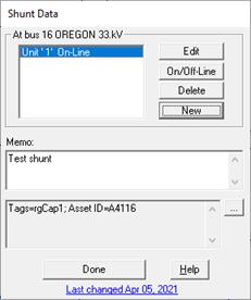
A dialog box will appear asking you for the shunt data. . .

Click on the … button near the upper right corner of the text area below the Memo field to open the Supplemental Object Properties dialog box with a data grid to enter data for the following data fields:
3. Tags: Enter list of tag strings separated by semicolon. The tags are for organizing objects that are related for some purpose. Please see documentation for Network | Apply Tag for more information.
4. User-defined fields: These are custom data fields that are defined by the user. Please see documentation for File | Preferences for information about how to specify the template for these data fields.
TO ADD A SHUNT UNIT:
1. Click on the "New" button to add a new shunt unit to the bus.
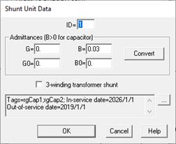
A dialog box will appear asking you for the shunt unit parameters. .

Input the shunt unit identifier in 'ID'.
The ID is a 2-character identifier used to differentiate between different shunt units on the same bus. The program automatically initializes the ID of a new shunt unit to a numeric value that has not been used by another unit on the same bus.
Input the shunt parameters.
You can input the positive and zero sequence admittances of the shunt directly.
G, B: Positive-sequence admittance in per unit. Set both G and B to zero for a zero-sequence shunt, such as a zigzag grounding transformer.
G0, B0: Zero-sequence admittance in per unit. Set both G0 and B0 to zero for an ungrounded shunt.
If you want to derive the admittances from the MW and MVAR ratings of the shunt, click on the "Convert" button.
The 'Convert Shunt Data' dialog box will convert the MW+ j MVAR load consumption to the equivalent per-unit admittances G + j B. You must enter the values G0 and B0 manually.
Click on the "3-winding transformer shunt" check box if the shunt is part of the T model of a 3-winding transformer.
In the printed output, OneLiner will show the tertiary circulating current for the transformer when the "3-winding transformer shunt" option is chosen. It has no other effect on the solution or on the output.
See Section 4.2 GENERATORS, LOADS,AND SHUNTS for the shunt model.
Click on the … button near the upper right corner of the text area below the 3-winding transformer shunt check box to open the Supplemental Object Properties dialog box with a data grid to enter data for the following data fields:
In/Out of service date: Click on the … button and enter the desired dates. See the Details and Techniques section “In/Out of service and tags” for more information.
Tags: Enter list of tag strings separated by semicolon. The tags are for organizing objects that are related for some purpose. Please see documentation for Network | Apply Tag for more information.
2. Repeat step 1 for each new unit. When done, click on OK to close the shunt dialog box.
The selected bus symbol will remain highlighted and a new shunt symbol will be shown attached to the bus.
TO EDIT OR DELETE A SHUNT UNIT:
1. Select the shunt.
Click the left mouse button once on the shunt to which you want to add a shunt unit.
2. Select the Network | Properties command.
A dialog box will appear listing all the units that are within this shunt.
3. Click on a shunt unit.
4. Press On/Off-Line to toggle a shunt unit from off-line to on-line or vice versa.
5. Press Edit to change the parameters of the shunt unit.
6. Press Delete to delete a shunt unit.
7. When done, press Done in the Shunt dialog box.
Main Window
NETWORK MENU