 on the Device Palette. The cursor will become a cross with a generator
symbol attached to it.
on the Device Palette. The cursor will become a cross with a generator
symbol attached to it.The New | Generator command in the Main Window lets you add a new generator to a bus. Each bus can have only one generator, but the generator may have up to 32 generating units. Different units within the same generator are differentiated by their 2-character identifiers. You can specify the impedance of each unit and whether it is on-line or off-line.
TO ADD A NEW GENERATOR TO A BUS FROM THE DEVICE PALETTE:
1a. Click on the New Generator button  on the Device Palette. The cursor will become a cross with a generator
symbol attached to it.
2a. Click on the One-line where you want to place the new generator.
Note: You can click on an existing bus to place the new generator on the bus. A bus can have at most one generator. The program will display an error message if the bus or node already has a generator.
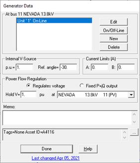
A dialog box will appear asking you for the parameters of the generator.
TO ADD A NEW GENERATOR TO A BUS USING MENU COMMAND:
1b. Select the bus.
Note: A bus can have at most one generator. This menu item is dimmed and cannot be activated if the bus already has a generator.
Click the left mouse button once on the bus to which you want to add a generator.
The bus symbol will turn dotted red when selected.
2b. Select the Network | New | Generator command.
A dialog box will appear asking you for the generator data.

3. Input the open-circuit voltage and the reference angle.
The magnitude and angle of the generator’s internal voltage source are used in flat-generator-voltages start option only. They have no effect in flat-bus and power-flow voltage start options.
Note: Instead of entering the reference angle manually, we suggest you use the Network | Set Generator Ref. Angle command to automatically set the reference angle of all the generators in the network. Please refer to the description of that command and see Section 4.9 for details.
4. Enter the current limits.
The generators can have two current limits. They are referred to as limit ‘A’ and limit ‘B’. These limits are designed to simulate type-3 wind turbines with doubly-fed generators. Version 15 has an improved model for Type-3 wind plants. We advise you to NOT create any more current-limited generators. Please see Section 4.10 for more information.
To enforce these limits in fault simulations you must (1) have the prefault-voltage option set to either “From a linear network solution” or “From a power flow solution”, and (2) turn on the “Enforce current limit” option in the Faults Simulation tab of the File | Preferences dialog box..
5. Select the type of power flow regulation. Click on:
Regulates voltage: The generator regulates the voltage magnitude at its own terminal bus or at another bus in a power flow solution.
Enter the target voltage magnitude (in pu) in the 'Hold V' edit box.
In the drop down list box, select the bus whose voltage magnitude is to be regulated by this generator.
Fixed P+jQ output: The generator's real and reactive power output is held constant in a power flow solution.
Note: These data fields are being used in the ASPEN Power Flow simulation only.
6. Enter a memo.
The memo is for any notes you wish to keep for this generator. It can have up to 512 characters.
Click on the … button near the upper right corner of the text area below the Memo field to open the Supplemental Object Properties dialog box with a data grid to enter data for the following data fields:
7. Tags: Enter list of tag strings separated by semicolon. The tags are for organizing objects that are related for some purpose. Please see documentation for Network | Apply Tag for more information.
8. User-defined fields: These are custom data fields that are defined by the user. Please see documentation for File | Preferences for information about how to specify the template for these data fields.
TO ADD A NEW GENERATING UNIT:
1. Click on the "New" button to add a new generating unit to the bus.
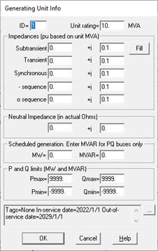
A dialog box will appear asking you for the generating unit parameters.

Input the generating unit identifier in 'ID'.
The unit ID is a 2-character identifier used to differentiate between different generating units on the same bus. The program automatically initializes the ID of a new generating unit to a numeric value that has not been used by another unit on the same bus.
This identifier can be used to mark the generating unit as a fictitious source generated by network equivalence. Refer to the COLOR | SPECIAL COLOR CODE COMMAND for further discussion.
Input the MVA rating of the generating unit in 'MVA'.
The generator impedances are based on this MVA rating, and NOT the system rating.
Input the following generating unit impedances: Subtransient impedance, transient impedance, synchronous impedance, negative-sequence impedance and zero-sequence impedance.
All the generating unit’s impedances must be based on its MVA rating.
As a shortcut, you can enter the subtransient impedance and press the Copy button to copy the same impedance to all the other impedance edit boxes.
Note: You can specify which impedance value (subtransient, transient or synchronous) will be used in the positive-sequence model for short circuit studies. Please refer to the Fault Simulation Tab of the File | Preferences command for more information.
Input the neutral impedance (in ohms) in 'Neutral Impedance …'.
Enter the actual neutral impedance without multiplying it by 3.
You can skip the rest of the generator-unit parameters if you are not interested in power flow simulation.
Enter the real power generation in MW.
Enter the reactive power generation in MVAR if the generator maintains constant P+jQ. The program ignores the MVAR generation if the generator maintains constant voltage.
Enter the following generation limits.
Pmax: Maximum real power output in MW.
Pmin: Minimum real power output in MW.
Qmax: Maximum reactive power output in MVAR.
Qmin: Minimum reactive power output in MVAR.
The Rating and the Pmin and Pmax limits are not used in this version of the program, but they may be used to limit the output of the system and area slack generators in later versions.
Click on the … button near the upper right corner of the text area below the P and Q limit fields to open the Supplemental Object Properties dialog box with a data grid to enter data for the following data fields:
In/Out of service date: Click on the … button and enter the desired dates. See the Details and Techniques section “In/Out of service and tags” for more information.
Tags: Enter list of tag strings separated by semicolon. The tags are for organizing objects that are related for some purpose. Please see documentation for Network | Apply Tag for more information.
Press OK to close the generating unit dialog box.
The generating unit you entered is listed in the list box as 'Unit 1' in the Generator dialog box. Subsequent generating units will be labeled 'Unit 2', 'Unit 3', and so on.
2. Repeat step 1 for each generator unit. Click Done to close the generator data dialog box.
The dialog box will disappear and a new generator symbol will be shown attached to the bus.
TO EDIT OR DELETE A GENERATING UNIT:
1. Select the generator.
Click the left mouse button once on the generator to which you want to add a generating unit.
2. Select the Network | Properties command.
A dialog box will appear listing all the units that are within this generator.
3. Click on a generating unit.
4. Click on On/Off-Line to toggle a generating unit from off-line to on-line or vice versa.
5. Click on Edit to change the parameters of the generating unit.
6. Click on Delete to delete a generating unit.
7. When done, press the Done button in the Generator dialog box.
Main Window
NETWORK MENU