 on the Device Palette. The cursor will become a cross with a bus symbol
attached to it.
on the Device Palette. The cursor will become a cross with a bus symbol
attached to it.The New | Bus command in the Main Window lets you add a new bus to the network. To execute this command you must first select a position with the left mouse button. The 'bus' object is linked to circuit breaker information. You can add new breakers with this command, also.
TO ADD A NEW BUS FROM THE DEVICE PALETTE:
1a. Click on the New Bus button  on the Device Palette. The cursor will become a cross with a bus symbol
attached to it.
2a. Click on the One-line where you want to place the new bus.
A dialog box will appear asking you for the parameters of the bus.
TO ADD A NEW BUS USING MENU COMMAND:
1. Select the bus location.
Click the left mouse button once at the desired position of the new bus.
2. Select the Network | New | Bus command.
A dialog box will appear asking for the parameters of the new bus.
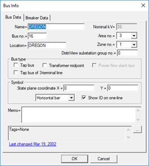
3. Input the bus parameters.
Name: A 16-character name for the bus. Any alphanumeric characters can be used, except '#', '$' and the string delimiter (single or double quotation mark). The first 12 characters of the name must be unique among all the buses in the network.
Nom. kV: Nominal line-to-line bus voltage.
Bus. No.: The bus number, if not zero, must have a unique value in the range 1 to 9999999, inclusive. You will get a warning if the bus number you chose is already in use.
Location: A 24-character location name. Any alphanumeric characters can be used, except the string delimiter (single or double quotation mark). The program does not make use of this datum at this time. It is for informational purposes only.
DistriView substation group no.: The group number must be between 0 and 999, inclusive. Enter a non-zero group number to designate this bus as a “substation bus”. Please refer to the documentation of the EXPORT | SUBSTATION DATA COMMAND for explanation of the substation group number.
Area no.: An area number between 0 and 9999, inclusive.
Zone no.: A zone number between 0 and 9999, inclusive.
4. Select the bus type.
Mark the check box labeled “Tap bus” if this dialog box is for a tap bus.
Tap buses are commonly used to break down a transmission line into sections. The algorithm for determining the make-up of a multi-section line is described in Section 8.9.
Mark the check box labeled “Tap bus of 3-terminal line” if this dialog box is for the center tap bus of a 3-terminal line.
When you mark this check box, the “Tap bus” checkbox will be marked also.
Mark the check box labeled “Transf. Midpoint” if this dialog box is for the fictitious midpoint bus of the T circuit of a 3-winding transformer.
This option is designed primarily for users who work with network data of ANAFAS format.
For Power Flow only: Mark the check box labeled “Power Flow slack bus” if this dialog box is for a slack bus.
You must designate a generator bus in each island to be the slack bus. An island is a set of contiguous network objects connected through lines, transformers, phase shifters and switches. Islands that are connected by dc lines must each have their own slack bus.
The generator at the slack bus cannot have current limits, and it cannot be a voltage-controlled current source.
5. Optional: Enter state plane coordinates
The state-plane coordinates are floating point numbers that specify the geographical location of the bus. You can use the Diagram | Snap to State Plane Coordinates command to automatically place all the buses on the one-line diagram.
6. Select the bus symbol style from the pull-down list
Bus symbol can be vertical bar, horizontal bar or dot.
7. Select whether or not to show the bus ID on the one-line diagram.
You must mark the “show ID on one-line” check box to see the bus ID (name, number and nominal kV) and solution voltages on the one-line diagram for short circuit and power flow simulations.
8. Enter a memo.
The memo is for any notes you wish to keep for this bus. It can have up to 512 characters.
Click on the … button near the upper right corner of the text area below the Memo field to open the Supplemental Object Properties dialog box with a data grid to enter data for the following data fields:
9. Tags: Enter list of tag strings separated by semicolon. The tags are for organizing objects that are related for some purpose. Please see documentation for Network | Apply Tag for more information.
10. User-defined fields: These are custom data fields that are defined by the user. Please see documentation for File | Preferences for information about how to specify the template for these data fields.
11. Click on the 'Breaker Data' page.
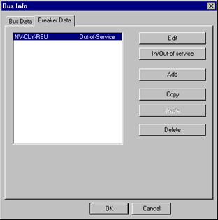
The 'Breaker Data' page is for circuit breakers that are linked to this bus. If there are any breakers at this bus, their names will appear in the list box on the left.
For the ‘Copy’, ‘Paste’ and ‘Delete’ functions, you can select one or more items in this list box. For the ‘Edit’ and “In/Out-of-service” buttons, however, you should select one, and only one, item.
TO EDIT BREAKER INFORMATION:
1. Select a breaker in the list and click on Edit’ to edit or view its parameters.
TO TOGGLE BREAKER IN/OUT-OF-SERVICE
1. Select one or more breakers in the list and click on "In/Out-of service”.
The program will toggle the status of the selected breakers. In-service breakers will become out-of-service, and out-of-service breakers will become in-service. The breaker-rating logic will ignore out-of-service breakers.
TO ADD A BREAKER:
1. Click on "Add" to add a circuit breaker to this bus.
A dialog box will appear.
2. Enter the circuit breaker name.
The circuit breaker name is limited to 12 characters.
3. Click on the 'Rating method' drop down list box and select either:
IEEE - Symmetrical current: for breakers that are rated on a symmetrical-current basis using ANSI/IEEE standards. Most breakers made in the US after 1964 are rated this way.
IEEE - Total current: for breakers that are rated on a total-current basis using ANSI/IEEE standards. Breakers made in the US before 1965 are rated this way.
IEC: for breakers rated using IEC standards. Breakers made by European manufacturers are rated this way.
When in doubt, you can identify the breaker type by examining the nameplate. The rating for an IEEE total-current rated breaker is in MVA, whereas the rating for an IEEE symmetrical-current rated breaker is in amperes. The nameplate for an IEC breaker usually shows both rated breaking current and rated making current in amperes.
The appearance of the dialog box depends on the rating method.
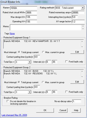
ANSI/IEEE total-current rated breaker properties screen:
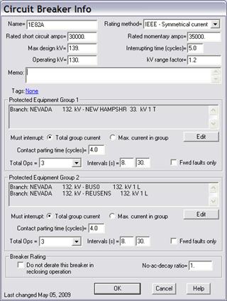
ANSI/IEEE symmetrical-current rated breaker properties screen:
IEC rated breaker properties screen:
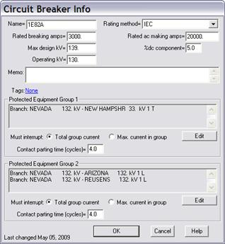
4. Enter the circuit breaker capabilities:
For breakers that are rated using ANSI/IEEE standards, enter ‘Rated short circuit MVA’ (Total-current rated breakers) or ‘Rated short circuit amps’ (Symmetrical-current rated breakers), and ‘Rated momentary amps’. All the current ratings must be entered as RMS values.
Note: Momentary current rating of breakers rated on symmetrical current basis is usually not listed on the nameplate and is assumed to be 1.6 times the short circuit rating. In such cases, enter N/A in ‘Rated momentary amps’ edit box.
For breakers that are rated using IEC standards, enter ‘Rated breaking amps’, ‘% dc component’ and ‘Rated ac making amps’.
5. Enter the breaker’s maximum designed kV or rated kV in ‘Max design kV’ box.
6. Enter the breaker’s operating voltage in 'Operating kV'. The default value of this quantity is the nominal kV of the breaker bus.
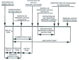
7a. Enter breaker interrupting time in cycles for breakers that are rated using ANSI/IEEE standards.
The speed of the breaker is commonly characterized by its interrupting time. A “4-cycle breaker”, for example, is a breaker that has an interrupting time of 4 cycles.
The interrupting time is the time between energization of the trip circuit to the extinction of the arc on the primary contacts. The interrupting time includes the breaker opening time and arcing time. Breaker interrupting time should be between 0 and 8 cycles.
7b. Enter rated short-circuit current percent dc component for breakers that are rated using IEC standards.
8. Enter the voltage range factor, K, for breakers that are rated using ANSI/IEEE standards.
The voltage range factor defines a range of voltages within which the breaker’s interrupting capability is inversely proportional to the operating voltage. When K equals 1, the interrupting capability is equal to the rated interrupting capability regardless of the operating kV.
The factor ‘K’ is not used for IEC rated breakers.
9. Enter a memo.
The memo is for any notes you wish to keep for this breaker. It can have up to 512 characters.
10. Press the text in blue, to the right of the label ‘Tags’ to enter one or more tags for this breaker.
The tags are for organizing objects that are related for some purpose. Please see documentation for Network | Apply Tag for more information.
11. Within each of the two Protected Equipment group boxes, enter equipment that the breaker must protect.
The breaker is said to “protect” a piece of equipment if it must open the circuit to interrupt current that flows to or from the equipment in a fault. Protected equipment can be lines, transformers, generators or buses in OneLiner short circuit model. In substations, circuit breakers are usually connected so that a single breaker can protect several pieces of equipment at the breaker bus. For added flexibility in modeling complex breaker connections, you can specify up to two separate groups of protected equipment for each breaker. The two protected equipment groups can have different contact parting time and reclosing parameters. For each group you can also specify list of additional branch outages to be applied in calculating group short circuit current. See Breaker Rating Application Guide for examples of protected equipment list in common breaker configurations.
Click on the Edit button within each protected equipment group box to change the list of equipment.
The following dialog box will appear.
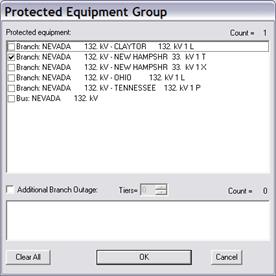
The list includes the breaker bus and all generators, shunts, and branches found in the vicinity of the breaker bus. The list does not include equipment that belongs to the other protected equipment group of this breaker.
Select the check box in front of the equipment name to add it to the group.
Select the check box Additional Branch Outage and select the check box in front of the equipment name to add it to the additional outage list. The program will include these branch outages when calculating short circuit current flowing to and from protected equipment in this group.
Each group can contain up to total 10 protected equipment and branch outages.
Click on OK to close the Protected Equipment dialog box.
12. Within each of the two Protected Equipment group boxes, click on “Total group current” if the breaker must interrupt the sum of currents flowing through all the equipment in the list. Bus tie breaker is a typical example where breaker must be checked with ”Total group current”.
Click on “Max. current in group” if the breaker must interrupt the current flowing through each of the equipment listed.
13. Within each of the two Protected Equipment group boxes, enter the breaker’s contact parting time for fault on devices protected by this breaker.
The contact parting time is the time between the initiations of short circuit and the parting of the primary arcing contacts. The contact parting time includes the relay tripping delay and breaker opening time. Breaker contact parting time should be between 0 and 12 cycles. Following table shows typical minimum contact parting time (without relay tripping delay) for different breakers:
8-cycle breaker: minimum contact parting time 4 cycles.
5-cycle
breaker: minimum contact parting time 3 cycles.
3-cycle breaker: minimum
contact parting time 2 cycles.
2-cycle breaker: minimum contact parting time
1.5 cycles.
14. Within each of the two Protected Equipment group boxes, select the number of total operations and enter the reclosing intervals in seconds for breakers that are rated using ANSI/IEEE standards.
15. Within each of the two Protected Equipment group boxes, select the check box ‘Forward Faults Only’ to indicate that the reclosing action takes place only when fault is on the protected equipment side of the breaker.
15. Mark the ‘Do not derate breaker in reclosing operation’ check box, if applicable, for breakers that are rated using ANSI/IEEE standards.
Note: The rated interrupting capabilities of only oil circuit breakers and air magnetic circuit breakers need to be derated for reclosing. SF6 breakers are usually not derated for reclosing.
16. Enter the ‘No-ac-decay ratio’ (NACD) for breakers that are rated using ANSI/IEEE standards.
The No-ac-decay ratio is defined as:
NACD = (Itotal - Ilocal)/Itotal
Where:
Itotal is the breaker short-circuit current.
Ilocal is the short-circuit current from local generators that are located no more than “one transformation” away or have external reactance in series that is less than 1.5 times the generator subtransient reactance.
The default value for NACD ratio is 1, which implies that short-circuit currents come entirely from remote sources and have no ac decay. This always yields a conservative breaker duty.
For in-depth breaker duty studies, the NACD ratio can be determined by simulating short circuits with and without local generators in service and calculating NACD as the ratio of breaker current in the with and without cases. This method will yield a breaker duty that is lower than, or equal to, the duty in the case when NACD is set to 1.
17. Press OK to close the 'Breaker Info' dialog box.
TO COPY BREAKER DATA TO CLIPBOARD
1. In the Breaker Data tab of the Bus Dialog Box, select one or more breakers in the list and click on "Copy”.
The program copies the breaker data to Window’s clipboard.
TO PASTE BREAKER DATA FROM CLIPBOARD
1. In the Breaker Data tab of the Bus Dialog Box, click on "Paste” to paste breaker data. This button is grayed and cannot be activated if there is no breaker data in Window’s clipboard.
A breaker info dialog will appear to allow data input on new breaker name and connection information.
Note: Protected Equipment group information will not be copied when breaker is being pasted to a different location.
TO DELETE A BREAKER:
1. In the Breaker Data tab of the Bus Dialog Box, select in the list box breakers that you want to delete and click on "Delete" to remove the circuit breakers.
TO CLOSE THE BUS INFO DIALOG BOX:
1. When you are done editing bus and breaker data, click on OK to close the 'Bus Info' dialog box.
The dialog box will disappear and the symbol for the new bus will appear on screen.
Main Window
NETWORK MENU