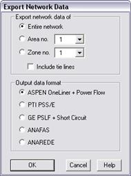
The Export | Network Data command in the Main Window lets you create a new data file that corresponds to the current state of the network. The exported file is a text file in one of the following formats:
•ASPEN text data file format (see Section 9.1 DXT NETWORK DATA FORMAT)
•Siemens PTI PSS/E format, ANAFAS format
•ANAREDE format
•GE Short Circuit (SCSC) and Power Flow (PSLF) format.
If you are planning to export to the PTI, GE or ANAFAS format, we suggest you first execute the Check | DATA COMPATIBILITYxe "PTI Format:compatibility with" COMMAND to see if there are any data incompatibilities, and, if there are any, fix them before you export the data.
The program will perform certain fix-ups during a PTI, GE, ANAFAS or ANAREDE conversion:
•Buses with zero bus number are given a unique positive bus number. These bus number assignments are temporary.
•Branches and generating units with blank circuit IDs are given an ID of ‘1’. The ID assignments are temporary.
•Switches are exported as lines with a very small reactance.
•For ANAFAS conversion only: Phase shifters and dc lines are ignored.
•For conversion to PTI version 30 or lower: Multiple shunt units on a bus are lumped into a single shunt. Generator and load units are not aggregated.
•3-Winding transformers are converted to the standard T model. The T-model conversion is temporary and does not affect the existing 3-winding transformer parameters.
Note: The exception to this rule is PTI PSS/E version 27 and later: Each 3-winding transformer in ASPEN is exported as a 3-winding transformer object in the PTI format.
•For GE Conversion only: For bus shunts, the letter ‘b’ is added to the beginning of the ID of shunts (if the ‘b’ is not there already). All bus names are truncated to 8 characters. Also, branch names are truncated to 8 characters and are exported as the branches’ “long ID”. All these changes are temporary.
The graphical information of the one-line diagram is not included in the exported file.
TO EXPORT NETWORK DATA TO A NEW TEXT DATA FILE:
1. Select the File | Export | Network Data command.
A dialog box will appear.

Note: This menu item is dimmed and cannot be activated after you have deleted one or more objects.
2. Select either the entire network or an area or a zone.
Click on the radio button "Entire Network" to export everything.
Click on the radio button "Area no.". Then, select an area in the drop down list box to export only the equipment within that area.
Click on the radio button "Zone no.". Then, select a zone in the drop down list box to export only the equipment within that zone.
3. Mark the ‘Include tie lines’ check box to include them in the text data file.
This option is meaningful only if you are exporting network data from a single area or zone. A “tie line” is a branch that spans the selected area or zone and one of its neighbors. When this option turned on, the program will export tie lines and their terminal buses, even though one of the tie-line bus terminals does not belong in the selected area or zone.
4. Select the output data format. Click on:
ASPEN: To export the network data using the ASPEN format.
PTI: To export the network data using the PTI PSS/E format of version 23 through 35.
GE PSLF+Short Circuit: To export the network data using the GE Power Flow (PSLF) and short circuit (SCSC) format of version 14.
ANAFAS: To export the network data using the ANAFAS format with 5-digit bus numbers. In 2021, we added the ability to store the NUN and NOP parameters as user-defined parameters. Converter-Interfaced Resources are exported to the DEOL section.
ANAREDE: To export the network data using the ANAREDE format.
5. Press OK.
IF YOU SELECTED THE ASPEN, ANAFAS OR ANAREDE FORMAT:
A dialog box will appear asking you to name the new data file.
Use the controls in the standard file dialog box to specify the name of the new data file.
The default file extension is shown at the bottom of the dialog box.
The TTY Window will appear on top of the Main Window to inform you of the program's progress.
Skip the rest of the instructions for this command.
IF YOU SELECTED THE GE FORMAT:
Two dialog boxes will appear asking you to name the new power flow data file with .EPC extension, and the new short circuit data file with .SEQ extension.
Use the controls in the standard file dialog box to specify the name of the new data files.
The TTY Window will appear to inform you of the program's progress.
Skip the rest of the instructions for this command.
IF YOU SELECTED THE PTI FORMAT:
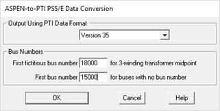
A dialog box will appear asking you to specify the PTI version number and starting bus numbers.

Select the PTI format you want.
Enter first fictitious bus numbers: This parameter is used only for version 26 or earlier. The program will assign bus numbers to the midpoint us of the equivalent T model of 3-winding transformers starting with this number, unless you have specified a nonzero fictitious bus number in the 3-winding transformer dialog box.
Enter first bus number for buses with no bus number. The program will assign bus numbers, starting with this number, to buses with bus number 0. The number you enter must be smaller than 99998.
Press OK to close the "ASPEN-to-PTI…" dialog box and commence data conversion.
A dialog box will appear asking you to specify the name of the new Raw Data file with .raw extension, and the new Sequence Data File with .seq extension.
Use the controls in the standard file dialog box to specify the name of the PTI Raw and Sequence Data files.
Press OK.
Main Window
FILE MENU