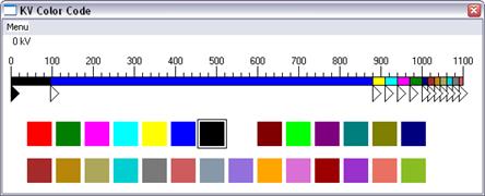
The Color | kV Color Code command lets you customize the appearance of the one-line diagram by using colors to distinguish network elements within different voltage ranges. You can also use this command to hide equipment in certain voltage ranges by giving them the color "invisible". (Note: Coloring equipment "Invisible" has no effect on the system. These changes affect only the visual appearance of the one-line diagram and DO NOT remove, delete or take out of service any equipment.) As OneLiner draws the one-line diagram, it colors each piece of equipment according to the follow logic:
if ( The equipment is a fictitious branch or generator ) {
if ( The color* for fictitious branch or generator is not "invisible" ) {
Draw with the special color for this type of equipment.
}
} else if ( The equipment has (or does not have) certain special tags ) {
if ( The color* for special tags is not "invisible" ) {
Draw with the special color for this type of equipment.
}
} else {
if ( The equipment is a branch ) {
if ( All the end buses of the branch have visible colors ) {
Draw each portion of the branch with the color corresponding
to
the kV of the
end bus to which it is attached.
} else if ( Only one end bus of the transformer has a visible color ) {
Draw the visible half normally and the invisible
half
with dotted
lines.
}
} else {
if ( The equipment has a visible color ) {
Draw the equipment with the color according to its kV value.
}
}
}
*Note: You can assign these colors with the Diagram | COLOR | SPECIAL COLOR CODE COMMAND.
TO ASSIGN COLORS TO DIFFERENT kV RANGES:
1. Select the Diagram | Color | KV Color Code command.
A window will appear to show you the current color assignments.

The dialog box has a horizontal ruler with markings between 0 kV and 1100 kV. Thirteen triangular knobs are attached to the bottom of the ruler marking the kV ranges. One of the knobs will be colored and a square with its color will be highlighted in the lower portion of the dialog box.
2. Select the kV range.
Click the left mouse button on the triangular knob at the minimum value of the kV range and drag it to the new desired voltage.
All the knobs can be dragged except for the leftmost one. Each knob controls the maximum voltage of the kV range to its left and the minimum voltage of the kV range to its right. As the knob is dragged, its position is shown at the upper left corner.
3. Select the color of the kV range.
Click the left mouse button once on the triangular knob at the minimum value of the kV range. The knob will become highlighted. Click the left mouse button once on the new color square.
The knobs and the ruler will be drawn to show the new selection.
The program will redraw the one-line diagram as you are making changes to the color and to the kV range.
4. Select the Menu | OK command to close this window.
Main Window
DIAGRAM MENU