Logic schemes are linked to the relay-group object. You can add or edit a logic scheme within the Protection Logic tab of the relay-group dialog box. (See documentation for the Relay | RELAY GROUP xe "Properties:relay group"PROPERTIES COMMAND in Section 3 for more information on the relay-group dialog box.)
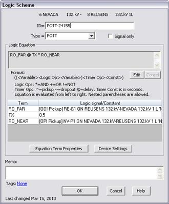
The dialog box for a logic scheme looks like this:

CREATING A NEW LOGIC SCHEME:
1. Enter scheme ID:
The ID is 20-character name for the scheme. The ID only has to be unique among logic schemes in the same relay group.
2. Select a scheme or “Custom” from the drop-down combo box:
A SCHEME OTHER THAN “CUSTOM”
The trip-equation template for the selected scheme will appear in the edit box.
CUSTOM SCHEME
Press the Edit Button and enter the logic equation in the edit box.
3. Mark the Signal Only check box if the logic scheme is used as part of another logic scheme equation, and it is not used to trip any circuit breakers directly.
4. Edit the logic equation as needed:
Press Apply when finished. If there are no errors, the terms of the logic equation will appear in the list box below.
5. Specify logic variable:
Click on a term in the list that is not a constant. Press Equation Term Properties.
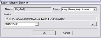
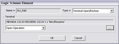
A Logic Scheme Element dialog box will appear.
At the upper right corner, specify the type as either “Relay Element/Logic Scheme” or “Terminal Open/Reclose”.
IF YOU SELECTED “RELAY ELEMENT/LOGIC SCHEME”

Click on the button labeled ‘…’ next to the Device edit box. The relay selection dialog box will appear.
Use controls in relay selection dialog box to select the desired relay.
Select relay element or zone and pickup or trip signal type from the combo dropdown list under the device edit box. Following is the list of available relay elements code:
•DTn: Overcurrent definite time element level n
•INST: Overcurrent instantaneous element
•INST/DT: Overcurrent instantaneous or definite time element of any level.
•TOC: Overcurrent inverse time element
•ZONE n: Distance relay zone n
The PICKUP signal will assert as soon as the relay element detects a fault. The TRIP signal will assert when the relay element trips after the element delay timer had finished counting.
IF YOU SELECTED “TEMINAL OPEN/RECLOSE”

Click on … button next to the Device edit box. The branch-selection dialog box will appear.
Use controls in branch-selection dialog box to select the desired branch terminal.
The Terminal-Open signal asserts when the select branch terminal is opened by a branch-end-opening fault or a branch outage operation.
Select the desired branch opening or reclosing operation in the drop-down combo box at the lower left corner of the dialog box.
6. Specify constants:
Click on a term in the list that is a constant, such as a time delay. Press Equation Term Properties.
The dialog box for a delay constant looks like this:

Enter the value of the constant in Value edit box. Delay time constant, which is common in logic-scheme equations, is always in seconds.
7. Edit relay element settings:
Click on a relay-element term from the list box.
Press Device Settings to open the corresponding relay dialog box to view and/or edit the relay settings.