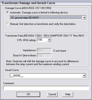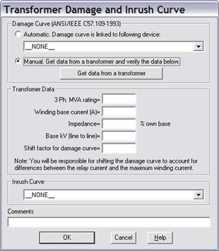
The Add | Transformer Damage Curve command in the OC Curves Window lets you add a transformer damage curve and an inrush curve to the overcurrent-relay plot. The transformer damage curve conforms to the ANSI/IEEE C57.109 standard of 1993. You can enter the damage- and inrush-curve parameters manually or have OneLiner compute them for you automatically.
You can use automatic option if (1) the transformer has at least one relay group that contains a fuse, relay or recloser, and (2) one or more of these protective devices are being displayed in the OC Curves Window. Under the “automatic” option, the program automatically shifts the damage curve by the ratio:
Relay current in primary amps / Maximum winding current
This extra adjustment is the key to drawing the transformer damage curve correctly for all fault types and winding configurations.
We recommend that you use the automatic option whenever possible.
Under the “manual” option, you must enter the 3-phase MVA rating, the winding base current, the leakage impedance and the nominal kV. You will also be responsible for shifting the damage curve correctly to account for the difference between the relay current and the maximum winding current.
The inrush curve can be plotted as set of points or as a continuous curve. Inrush current withstand time are taken from the “Electrical Distribution System Protection” handbook, published by Cooper Power Systems, 1990. You can also select the plot extent to 0.1 or 10 seconds. The inrush curve is not adjusted by the ratio of the relay current or the maximum winding current.
TO ADD DAMAGE CURVE AND INRUSH CURVE USING THE AUTOMATIC FEATURE:
1a. Select the Add | Transformer Damage Curve command.
When the dialog box appears, click on the radio button labeled “Automatic”.

Note: The Add | Transformer Damage Curve command is gray and cannot be activated if there are already six damage curves on the plot. The Automatic radio button is gray and cannot be selected if none of the protective devices being shown on the plot is in a relay group that resides on a transformer terminal.
1b. Select a protective device in the drop-down list box immediately below.
A device is include in the list if (1) it is a relay, fuse or recloser whose curve is being plotted in the OC Curves Window, and (2) the device is in a relay group that resides on the primary, secondary leg of a 2-winding transformer or (3) on the wye-connected winding leg of a 3-winding transformer. Once you link the damage curve to a protective device, OneLiner deduces, from the location of the relay group, which side of the transformer winding (primary, secondary or tertiary) the damage curve is intended.
Several transformer parameters are copied to the transformer-data group box below.
Note: Protective devices on 3-winding transformers are restricted to those with wye-wye-delta and wye-wye-wye winding configurations.
1c. Verify the 3-phase MVA rating.
Make sure the MVA Rating being shown in the “3-Ph. MVA rating” drop-down combo box is the correct 3-phase ‘OA’ rating for the transformer side you selected implicitly in step 1b.
The ratings in this drop-down combo box are the ‘MVA1’, ‘MVA2’, ‘MVA3’, and the ‘MVA base’ of the transformer. (Ratings that are equal to zero are omitted.) If none of these is the correct rating, you can enter the 3-phase MVA rating of the winding into the edit box by hand. As you change the MVA rating, the program will update the winding impedance automatically.
1d: Very Important: The position of the damage curve will vary by fault type.
Under the automatic option, OneLiner will automatically shift the damage curve to account for the difference between the relay current and the maximum winding current when a fault solution is being displayed with the Show | Relay Operations for One Fault command.
The classical example is a delta-wye distribution transformer, with the delta winding on the high side. When a single-line-to-ground fault is applied to the low side, the current sensed by a relay on the high side is the same as the maximum current on the delta winding. When a 3-phase fault is applied, the relay current on the high side is a factor of 1.732 higher than the maximum winding current. This causes the 3-phase-fault damage curve to be plotted to the right of the single-line-to-ground damage curve by a factor of 1.732.
Skip to step 4 below.
TO ADD DAMAGE CURVE AND INRUSH CURVE MANUALLY:
2a. Select the Add | Transformer Damage Curve command.
When the dialog box appears, click on the radio button labeled “Manual”.
Note: The Add | Transformer Damage Curve command is gray and cannot be activated if there are already six damage curves on the plot.

2b. Press the “Get data from a transformer” button if you want the program to help you fill in the transformer data. Otherwise, skip to step 2c and enter the values by hand.
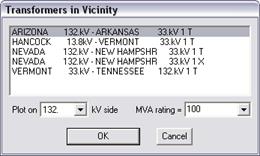
A dialog box will appear showing a list of 2- and 3-winding transformers in the vicinity of the first relay.

Select a transformer in the list by clicking on it.
Click on “Plot on” dropdown list to select the side of the transformer (primary, secondary or tertiary) that is being protected by the relay, fuse or recloser.
Select a rating in the “3-Phase MVA rating” drip-down combo box or type in a value by hand. Within the “MVA rating” dropdown list are the MVA base of the transformer, and its ratings MVA1, MVA2 and MVA3. If none of these is the correct rating of the transformer winding, you can enter the 3-phase ‘OA’ rating of the winding into the edit box by hand.
Press OK to close the “Transformers in Vicinity” dialog box.
OneLiner will fill in the four parameters within the Transform Data group box.
Make sure the transformer data are consistent with the following definitions.
3-Phase MVA Rating: The 3-phase MVA rating of the transformer winding on the side (primary, secondary, tertiary) of interest. We suggest you use the transformer’s ‘OA’ rating.
Winding Base Current: The 1 pu base current for an individual transformer winding, in amperes. You can compute the base winding current with this formula: M x 1000 / (3 * V) where M is the 3-phase MVA rating of the transformer winding, and V is the voltage in kV across an individual transformer winding when a 1 pu positive-sequence voltage is at the transformer terminal.
Impedance: The transformer leakage reactance in per unit based on the transformer's MVA rating. The value of X is between 5% and 15% for most transformers.
Base kV: The 1 pu line-to-line nominal kV at the transformer terminal. This parameter is used for the inrush curve.
Skip Step 2c and go to step 3.
2c. Input the damage- and inrush-curve parameters by hand.
Please see definition of the parameters in step 2b.
3. Input shifting factor for damage curve to account for the difference between the relay current and the maximum winding current.
The parameters of step 2 will yield a damage curve for the case where the maximum winding current is the same as the relay current. If this is not the case, then you need to shift the curve accordingly. This can be accomplished by entering a shifting factor that equal ratio of relay current / maximum winding current.
In the classical example cited in step 1d, you must enter factor of 1.732, for the damage curve on the delta side during a 3-phase fault.
4. Enter comments with up to 63 characters in 'Comments'.
The comments will be displayed on the screen as part of the curve identification.
5. Select one of following options in the “Inrush curve” combo box if you want the program to draw an inrush curve in addition to the damage curve.
•Plot as discrete points. Up to 0.1 seconds
•Plot as discrete points. Up to 10 seconds
•Plot as a curve. Up to 0.1 seconds
•Plot as a curve. Up to 10 seconds
Note: Under the log-log option, the inrush curve is always plotted as discrete points.
6. Press OK.
The dialog box will disappear and the transformer damage curve will be drawn on the plot.
Curves Window
ADD MENU