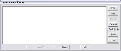
The Specify Simultaneous Fault Command in the Main Window lets you specify and simulate a fault with up to ten simultaneous unbalanced network modifications and short circuits. The program logic for this command is based on an algorithm developed by V. Brandwajn and W.F. Tinney in the early 1980s. With this method, any combination of simultaneous network modifications and short circuits can be solved with the same generality. After the simulation of a simultaneous fault, OneLiner will automatically display the solution on the one-line diagram.
TO SPECIFY A SIMULTANEOUS FAULT:
1. Select the Faults | Specify Simultaneous Fault command.
A dialog box with a large list box will appear. If you have simulated a simultaneous fault earlier in the session, the list box will contain your last simultaneous fault specifications. Otherwise, the list box is blank.

2. Load fault specifications from file
If you have not saved any fault specification to file, or if you wish to start from scratch, skip to step 3.
Press the Load button. A file open dialog box will appear.
Use the standard controls in the file open dialog box to select the file you would like to load and click Open. The fault specification files have extension of .FLT. The saved fault specification will be displayed in the list box.
3. If needed, press the Clear All button to remove all the network modifications and short circuits from the list box, so that you can start over from the beginning.
4. Press the Add button to add a network modification or a short circuit.
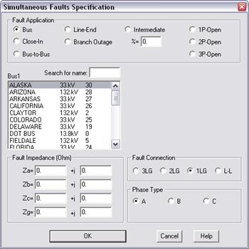
A Simultaneous Fault dialog box will appear.

Click on one of the radio buttons in the Fault Application group box to select a fault type: Bus fault, bus-to-bus fault, line-end fault, branch outage, intermediate fault, one-phase-open fault, two-phase-open fault, and 3-phase-open fault.
The appearance of the dialog box changes depending on the fault type. The picture shown above is for the bus fault. A second dialog box will appear for bus-to-bus fault and for other fault types involving branches.
Bus Fault: Select the bus to be faulted by clicking on its name in the list box. Then select the fault connection and phase type, and enter the fault impedances, if any.
Bus-to-Bus Fault (also called a crosscountry fault): Select the two buses to be shorted by clicking on their names in the two list boxes. Then select one of the entries under “Phase Type” to specify which phase of Bus1 is shorted to which phase of Bus2. Enter a fault impedance if there is a finite impedance between the two shorted phases.
Line-End Fault: Select the affected branch by highlighting the two bus terminals. The short circuit will be applied to the Bus2 side of the branch after the Bus2 end has been disconnected. Then select the fault connection and phase type, and enter the fault impedances, if any.
Branch Outage: Select the branch to be outaged by selecting the bus terminals in the two list boxes.
Intermediate Fault: Select the affected line by highlighting the two bus terminals. Enter the location of the fault by entering a percentage in the edit box labeled “%=”. The end of the branch you highlighted in the left list box (BUS1) is assumed to be 0%, and the other end 100%. Then select the fault connection and phase type, and enter the fault impedances, if any.
Phase-Open Faults: Select the affected branch by highlighting the two bus terminals. The phase-open fault will be on the side of the bus you highlighted in the left listbox (Bus1). Then, for 1-phase-open and 2-phase-open faults, select one of the entries under “Phase Type” to indicate which phase or phases are opened.
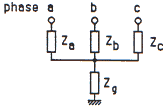
The fault impedances are based on the following diagram. For a 3-phase fault, all four impedances can be specified separately. For a 2-phase fault, only Zg and two of the other impedances can be specified. For a single-line to ground fault, only Zg and one of the other impedances can be specified. For a phase-to-phase fault, the impedance Zg is infinite, and only two of the impedances on the affected phases can be specified.

5. Repeat step 2 for all the network modifications and short circuits that you wish to simulate simultaneously.
There is a maximum of 10 network modifications and short circuits.
6. To review a network modification or short circuit you specified, click on an entry in the list box and press Edit.
To delete a network modification or short circuit you specified, click on an entry in the list box and press Delete.
Press the Save button to store fault specification list to a file. A file dialog will appear asking you to specify the file name.
When done, press Simulate to begin simulation.
OneLiner will present the fault solution in a graphical form on the one-line diagram, and in a text form in the TTY window.
Main Window
FAULT MENU