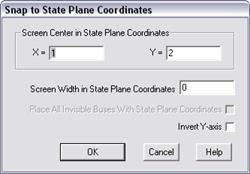
The Snap to State Plane Coordinates command in the Main Window re-positions all the buses according to their state-plane coordinates. This command also makes visible all the buses that have state-plane coordinates but were not placed previously.
Many users create their text data files by exporting information from their GIS database. If the buses’ state-plane coordinates are within these files, the user can use this command to place all the buses automatically according to their geographic location.
TO RE-POSITION ALL NODES USING THEIR STATE-PLANE OR GPS COORDINATES:
1. Select the Diagram | Snap to State Plane Coordinates command.
A dialog box will appear asking you to specify the screen parameters. The program will fill in the three edit boxes with estimates computed based on the coordinates available. These estimates work well in most cases. You can edit them if you wish.

2. Enter in 'X' and 'Y' the state-plane coordinate for the position being displayed at the center of your screen.
3. In 'Screen Width in State Plane Coordinates', enter the width of the computer screen in state-plane coordinates.
4. Mark the 'Place All Invisible Buses With State Plane Coordinates' check box to have the program place all hidden buses that have state-plane coordinates.
5. Mark the ‘Invert Y-axis’ check box if the program logic places the buses up side down.
6. Press OK.
The 'Snap to State Plane Coordinates' dialog box will disappear. All the buses with state plane coordinates will be re-positioned according to their coordinates. Buses and nodes with coordinate of (0,0) will not be moved.
Main Window
DIAGRAM MENU