The SIR Calculator command in the Main Window is designed to calculate the source impedance ratio (SIR) for a transmission line. SIR is the ratio of the source impedance behind the relay location to the impedance of the line. The SIR can be considered a measure of line length. According to the IEEE Guide for Protective Relay Application to Transmission Lines, a line is considered long if SIR is less than 0.5, medium if SIR is between 0.5 and 4.0, and short if SIR is greater than 4. The reference below discusses how this measure of line length affects the method of protection.
M.J. Thompson and A. Somani, “A Tutorial on Calculating Source Impedance Ratio for Determining Line Length,” presented at the 68th Annual Conference for Protective Relay Engineers at Texas A&M University, 2014. The paper is available from http://dx.doi.org/10.1109/CPRE.20115.7102207.
The implementation of this command is based on the “recommended method to calculate SIR” described in this paper.
TO CALCULATE THE SIR FOR A LINE:
1. Select the relay location on a line.
Right mouse click on a relay group if it is available. Otherwise, right mouse click on the line near the location where a future relay will reside. The line can have multiple sections connected by tap buses and closed switches.
2. Select the Faults | SIR Calculator command.
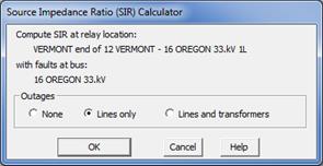
A dialog box will appear.

Select one of the three outage options: None, Lines only, and Lines and transformers. Press Ok.
A dialog box will appear asking you to specify the name of the report file in CSV format.
3. Use the controls in the standard file dialog box to specify the name of the report file. Press Save.
When finished, OneLiner will ask you if you want to view the report with a spreadsheet program.
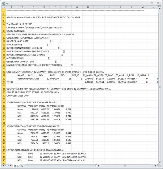
The report consists of the following sections:
•A list of line segments, their impedance in positive and zero sequence, and the K factor. Also, the line’s overall impedance in positive and zero sequence, and the K factor.
•A table showing the SIRs for phase protection with and without different branch outages behind the relay location.
•A table showing the SIRs for ground protection with and without different branch outages behind the relay location.
•A list of branch outages.
An example report is shown below.

Main Window
FAULTS MENU