The Show Solution On 1-Line command in the Main Window lets you display a post-fault solution and location directly on the one-line diagram. The quantities that can be displayed under this command include currents, voltages and relay operating times. The faults to be displayed must have been simulated previously using the Fault | Specify command. You can use the probe function to show the voltage and current phasor of network elements once a post-fault solution is displayed on the one-line diagram.
TO DISPLAY SOLUTION ON THE ONE-LINE DIAGRAM:
1. Select the Faults | Show Solution on 1-line command.
Note: The menu item is dimmed and cannot be activated if no faults have been simulated or if you have modified the network since the last fault simulation.
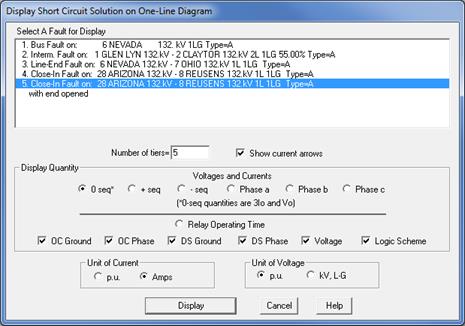
A dialog box will appear asking you to select the fault and the display options.

2. Select a fault.
Select the fault to be displayed by clicking once on the fault description in the list box.
You can select a fault by highlighting any part of its description.
3. Input the extent of the fault-solution display in the ‘Number of tiers' edit box.
The tier parameter determines the extent over which the post-fault network solution will be displayed. If you specify a tier limit of n (where n is a non-negative integer that does not exceed 9999), OneLiner will display the solution for buses and branches within n tiers of the fault. A large tier value may increase the screen refresh time slightly.
4. Mark the Show current arrows check box to display the current arrow with the branch current.
The direction of the current arrow is based on the phase angle of the current (rounded to the nearest 45-degree increment). The arrow is a useful visual aid in most cases. It may not be meaningful for line-to-line and certain other type faults.
5. Select quantities to be displayed.
Click on one of the following six radio buttons to display the sequence or phase voltages and currents.
0 seq: Zero-sequence voltages and 3 times the zero-sequence currents.
+ seq: Positive-sequence voltages and currents.
- seq: Negative-sequence voltages and currents.
Phase a: Phase-'a' voltages and currents.
Phase b: Phase-'b' voltages and currents.
Phase c: Phase-'c' voltages and currents.
Click on the "Relay Operating Time" radio button to display the relay operating times. The operating time shown for each relay group is the fastest tripping time among the device types you selected below:
OC Ground: Overcurrent ground relays and reclosers.
OC Phase: Overcurrent phase relays, fuses and reclosers.
DS Ground: Distance ground relays.
DS Phase: Distance phase relays.
Voltage: Voltage relays.
Logic scheme: Logic schemes.
6. Select the output display units.
You can skip this section if you are displaying relay operating times.
In the “Unit of Current” group box, mark the "p.u." radio button to display currents in per unit, or the “Amps” radio button to display currents in amperes.
In the “Unit of Voltage” group box, press the "p.u." radio button to display bus voltages in per unit, or the “kV, L-G” radio button to display voltages in kV, line-to-ground.
NOTE: OneLiner displays all fault current and voltage quantities in RMS value.
7. Click on the "Display" button.
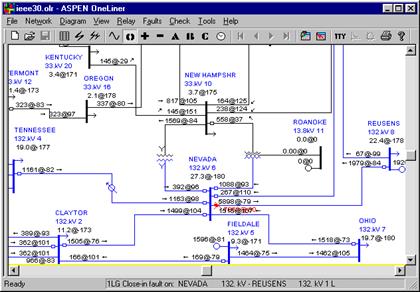
The dialog box will disappear and the one-line diagram will be redrawn to show the output of the quantities requested. If you are using the split-window feature, the solution will be displayed on both panes. A red “X” will appear at the location of the fault. The fault current being displayed will change depending on the quantity being shown. For example, the phase 'a' current is shown next to the fault location when phase 'a' quantities are being shown, regardless of the fault type. In addition, a summary of the fault is written to the TTY Window.
If voltages and currents are being displayed:
1. Voltages and currents are shown as complex numbers in polar form. The symbol that separates the magnitude and angle of the complex number denotes the quantity that is being displayed: 'A', 'B' and 'C' for a-, b-, and c-phase quantities and '@', 'P' and 'N' for zero-, positive- and negative-sequence quantities.
2. Bus voltages are shown immediately beneath the bus names and nominal kVs. The magnitudes are in either per-unit or kV (line-to-ground) and the angles are in degrees.
3. The generator currents are shown immediately above the generator symbols. The magnitudes are in either per-unit or amperes and the angles are in degrees. The angle of a generator current is between -90 and 90 degrees if it flows out of the generator and into the bus.
4. The branch currents are shown next to where the branch connects to the bus. The magnitudes are in either per-unit or amperes and the angles are in degrees. For branches near the fault, the current angle will be about -90 degrees if it is flowing out of the bus into the branch and about +90 degrees if it is flowing out of the branch into the bus. The branch arrows are shown after the branch currents to indicate the direction of current flow.

If relay operating times are being displayed:
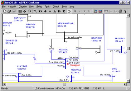
1. The relay operating time in seconds is shown above each relay group. The operating time is preceded by:
DIFF: if is from a line differential relay.
FU: if it is from a fuse.
OG: if it is from an overcurrent ground relay.
OP: if it is from an overcurrent phase relay.
OVT: if is from a voltage relay, operating on over-voltage
RG: if it is from a ground recloser.
RP: if it is from a phase recloser.
UVT: if it is from a voltage relay, operating on under-voltage.
ZG1, ZG2, ZG3 or ZG4: if it is from a ground distance relay. The numbers 1, 2, 3 and 4 are the zone numbers.
ZP1, ZP2, ZP3 or ZP4: if it is from a phase distance relay. The numbers 1, 2, 3 and 4 are the zone numbers.
XXXX: if it is from a logic scheme type XXXX.
2. The words 'No relay' are shown if the relay group has no relays of the type being displayed.
3. The quantity '9999s' is shown if none of the relays of the type being displayed has operated.

For a detailed look at the voltage and current phasors for the network elements, please refer to the Show Phasors command on the next page.
Main Window
FAULT MENU