The Show | Relay Operations for 1 Fault command in the DS Relays Window lets you show graphically the operations of the selected distance relays for a fault that was previously simulated.
TO SHOW RELAY OPERATIONS FOR A FAULT:
1. Select the Show | Relay Operations for 1 Fault command.
Note: The menu item is dimmed and cannot be activated if no faults have been simulated or if you have modified the network since the last fault simulation.
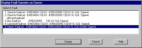
A dialog box will appear asking you to select a fault. The list box will contain all the faults that have been simulated.

2. Select a fault and then click on "Display".
If the fault description takes more than one line, you can select it by clicking on any one of those lines.
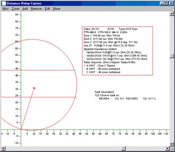
The dialog box will disappear and the window will be redrawn to show the apparent impedances. The program will simultaneously update the solution on the one-line diagram in the Main Window.
The fault description is shown below the relay parameter box. The apparent impedances that are plotted vary depending on the relay type. For most phase relays, the following 3 quantities are plotted:
B-C Unit: (Vb-Vc)/ (Ib-Ic)
C-A Unit: (Vc-Va)/ (Ic-Ia).
A-B Unit: (Va-Vb)/ (Ia-Ib)
For most ground relays, the following 3 quantities are plotted:
A Unit: Va / (Ia+3KIo)
B Unit: Vb / (Ib+3KIo)
C Unit: Vc / (Ic+3KIo).
Va, Vb, and Vc are the phase voltages. Ia, Ib, and Ic are the phase currents. Io is the zero sequence current. K = (Zo-Z1)/(3Z1).
Note: A ground relay has two K parameters: K1 (for zone 1) and K2 (for all other zones). The K that is used to draw the apparent impedances is K1.

Note: The graphical characteristics and the apparent impedances shown are for information purposes only. The logic that determines tripping is completely separate from the logic that draws the relay characteristics and the apparent impedances.
The outcome of the tripping logic is shown in text below the apparent impedances. It indicates which units are tripped and which are restrained. The units that are tripped are highlighted by a red check mark. The time delay is also shown. (Details on the tripping logic can be found in Section 2 of the Distance Relay Editor User’s Manual.)
The relay characteristics shown are the so-called “static” characteristics that assume no voltage memory. The actual tripping area can be larger than the static characteristics. It is possible, therefore, for a relay to trip when the apparent impedance is outside of the static characteristics. When in doubt, you should rely on the tripping results shown in text, and not on the graphical display of the relay characteristics or the apparent impedances.
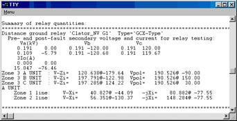
A summary of the fault is written to the TTY Window. This includes all of the operating quantities used to determine whether the relay trips or not. The relay test quantities (consisting of the currents and voltages before and after the fault) are also written to the TTY Window if the “Relay Test Quantities” option is selected within the Misc. | Options command.

DS Relays Window
SHOW MENU