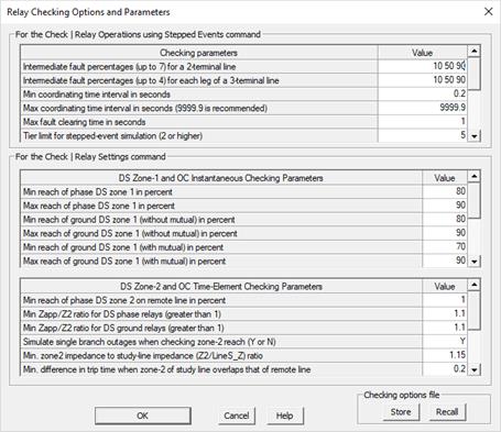
The Check | Relay Checking Parameters command in the Main Window is designed to help you manage the setting limits, checking options, and other parameters that are used by the Check | Relay Settings command and the Check | Relay Operations using Stepped Events command in the Main Window.
TO VIEW AND EDIT RELAY CHECKING PARAMETERS:
1. Select the Check | Relay Checking Parameters command.
A dialog box will appear. There are three data grids.
The top data grid is for parameters for the Check | Relay Operations using Stepped Events command.
The bottom group boxes are for the Check | Relay Settings command. The middle data grid is for checking distance relays’ zone-1 and for checking overcurrent relays’ instantaneous unit.
The bottom data grid for checking distance relays’ zone-2 and for checking overcurrent relays’ time elements.

The meaning of most of the entries is self-explanatory. The following explains the not-so-obvious parameters and options.
For the Check | Relay Operations using Stepped Events command
•Intermediate fault percentages for 3-terminal lines: The percentages are for each of the 3 line segments, starting from the center bus (0%) and ending at one of the three bus terminals (100%).
•Max fault clearing time in seconds: The timer begins at the on-set of the fault, and stops when the fault current drops to zero and the next event is a reclosing event. The program will compare this time against the value you entered, and it will issue a warning if the clearing time is too long.
•Treat switches at the ends of the study line as breakers: Users who have modeled their detailed breaker configurations using switches should set this option to ‘Y’. Otherwise, the program will report that “another branch tripped before the study line is cleared” whenever one of these switches opens. “N’ is the default.
•Stop stepped-event simulation when fault current is zero: This option, if set to ‘Y’, will end the stepped-event simulation when the fault current drops to zero, and the next event is a reclosing event. The default is ‘N’ because misoperations can happen following a reclosing event.
•Omit outaging a branch if its current in a bus fault is less than this many amps: At the very beginning of the execution of this command, and before any stepped events are simulated, the program simulates a 3-phase and a single-line-to-ground fault at the ends of the study line. A branch connected to the ends of the study line is removed from the outage list if the branch currents in both the 3-phase and single-line-to-ground fault are below a certain number of amps. This is designed to speed up the simulation of stepped events by not outaging stub lines and other branches that carry very little fault current. You must specify a value that is 1A or larger. The default is 1A.
•Max CTI for lines with dual pilot: This feature is for lines that are protected by a dual-pilot logic scheme that is not modeled in OneLiner. You can mark a line of this kind by giving a special tag to one of the relay groups at the ends of the line. (The default tag is “Sph2”. You can change it in the Relay | Options command.) For a line that is protected by dual pilot, the program will simulate a single event (with artificial relays tripping instantaneous on ends of the line) and look for over-reaching relays in neighboring branches that trip within a very small coordinating time interval of 5 cycles or less. You can change this 5-cycle threshold in this command. No branch outages are taken for dual-pilot lines.
•Allow single branch outages for lines with single pilot. This feature is for lines that are protected by a single-pilot logic scheme that is not modeled in OneLiner. You can mark a line of this kind by giving a special tag to one of the relay groups at the ends of the line. (The default tag is “Sph1” . You can change it in the Relay | Options command.) By default, no single or double branch outages are taken for single-pilot lines. OneLiner will take single branch outages only if you set this option to ‘Y’. The default is ‘N’.
•Fault-current threshold below which fault is considered cleared. If the total fault current exceeds this value after stepped events came to an end, you will get an additional warning message “The fault is not cleared”. This current could be caused by line shunts (G+jB of lines) or network anomalies. Increasing this threshold will eliminate these messages.
•Disconnect true ends of line when a mutual line segment is outaged. This parameter effects the simulation results only if you directed OneLiner to “Outage mutually coupled lines” and/or “Outage and ground ends of mutually coupled lines”. This setting is “Yes” by default, meaning that the program disconnects the true ends of a line -- and ground the true ends if you asked to ground the ends of mutually coupled lines -- if a segment of that line is mutually coupled to the study line. Set this parameter to “No” if the “line” outaged at both ends is causing some ground relays to trip when it its ends are grounded.
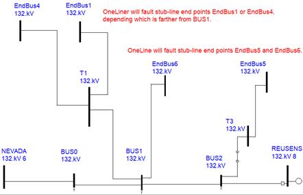
•For 2-terminal lines and stub lines only: Fault end of tapped lines if the ratio Ztapped-line/Zstudy-line exceeds a certain ratio. Ztapped-line is the positive-sequence impedance of the tapped line, and Zstudy-line is the positive-sequence impedance of the study line. (A ratio of 99 or higher will disable this function.) OneLiner will simulate a 3-phase fault on the end point of the tapped line and see if it is cleared by the relays on the study line. It is considered an error if the fault is not cleared, or if the relays that clear the fault are not from the study line.
Notes: A tapped line can be a radial network consisting of lines. (The first branch of the network can be a closed switch.) In that case, the bus faulted by OneLiner is the bus in the radial network that is farthest (in terms of positive-sequence impedance) from the tap bus. See picture below of a multi-section line with a number of tapped lines. For this network, the following buses will be faulted: EnBus4 or EndBus1 (whichever is farther from bus BUS1), EndBus6, and EndBus5. OneLiner will warn you if the relays at REUSENS do not trip on faults at any of these end buses.

•For 2-terminal lines and stub lines only: If you enter “Y”, OneLiner will consider any transformer as a tapped transformer if (1) it has no relays on any of its terminals and (2) it is connected directly to a tapped bus, or is connected to a tapped bus through a line or a closed switch. For a stub line, OneLiner will include, in addition, any transformer that is connected to the last bus of the stub line as a tapped transformer when it has no relays on its terminal. For each tapped transformer, OneLiner will simulate a 3-phase fault on the far end(s) of the transformer and make sure no relays in the network picks up on the fault. (We assume the transformer is protected by relays not in the network model.)
•Warn CTI violation only it is too low (Y or N). Enter “Y” to filter out messages that warn you that the coordinating time interval is too high.
For the Check | Relay Settings command
•Check reach of zone 1 on both remote legs of 3-terminal line. ‘Y’ is the default. In which case, zone-1 reach is check with a line that consists of the local leg plus the two remote legs, one at a time. If your choice is ‘N’, the program will check the zone-1 reach on a line that consists of the local leg plus the shorter of the two remote legs only. (“Shorter” here means less in line impedance.)
•Check reach of zone 1 only with the outage of the 3rd leg of 3-terminal lines. ‘Y’ is the default. This means whenever zone-1 reach is being calculated for relays on the local leg plus a remote leg, the remaining leg is always outaged. If your choice is “No”, zone-1 reach is also calculated for the case when both remote legs are in service.
The Store and Recall buttons at the lower right corner are designed to facilitate transmission of the relay checking parameters from one computer to another. Please first check to make sure that the same release version of OneLiner is installed on all the computers.
1. Press Store to save the relay checking parameters to a text file.
OneLiner will first perform a data check before proceeding. A standard file-save dialog box will appear to ask you for the file name. The standard file extension is “.txt”.
Enter a file name and press Save.
Note: Do not edit this text file. It is protected with a checksum.
2. Press Recall to retrieve the relay checking parameters from a text file.
A standard file-open dialog box will appear to ask you for the file name.
Select an existing file and press Open.
The new parameters will appear in the data grids.
3. Press OK to save the parameters to Window’s registry and close the dialog box.
Both the Check | Relay Settings command and the Check | Relay Operations using Stepped Events command retrieve the parameters and options from the Windows registry when they are executed.
Main Window
CHECK MENU