The Primary/Backup Relay Coordination command in the Main Window helps you check the coordination between coordinating pairs. The results are shown in a tabular form. The program flags any case in which the coordinating time interval (CTI) is outside the range of acceptable values. ,
This command works with primary and backup relays of virtually any combination of types (phase, ground, overcurrent and distance). This command can also be used to check the coordination between a relay and a recloser, taking into account the reset time of the relay.
There are six different “Extent” options available. You can check all the coordinating pairs in the system, or just those pairs that are within certain areas and zones, pairs of certain voltage class, etc.
Note: There is an alternative method for checking relay coordination that does not require primary/backup pairs. Please see the documentation of the Check | Relay Operations using Stepped Events command for details.
TO CHECK PRIMARY/BACK RELAY COORDINATION:
1. Optional: Select a relay group before issuing this command if you wish to check coordinating pairs involving a single relay group or if you wish to check coordinating pairs in the vicinity of a specific relay group.
Click the left mouse button once on a relay group.
The selected relay group will turn dotted red.
2. Select the Check | Primary/Backup Relay Coordination command.
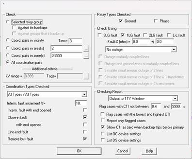
A dialog box will appear asking you to enter the checking criteria.

3. Specify the checking extent.
There are six options available. The first three options are grayed and cannot be selected if you did not select a relay group prior to issuing the command.
Selected relay group against its backups: Click on this option to check the relays within the selected relay group against relays in backup relay groups. This option is grayed if the selected relay group has no backups.
Selected relay group against relays that it backs up: Click on this option to check the relays within the selected relay group against relays in relay groups that are backed up by the selected group. This option is grayed the selected relay group is not backing up any relays.
Vicinity of selected relay group: Click on this option and enter a tier limit to check relay groups that are in the vicinity of the selected relay group. Set tier to ‘1’ to check coordinating pairs whose primary relay group is within one bus away, and ‘2’ for two buses away, and so on.
Area(s): Click on this option and enter the area numbers to check coordinating pairs whose primary relays are within the selected areas. The area string can contain a mixture of ranges and numbers, e.g., “3-5,6,7,10-12”. Press the button “…” on the right if you need help in composing the area string.
Zones(s): Click on this option and enter the zone numbers to check coordinating pairs whose primary relays are within the selected zones. The zone string can contain a mixture of ranges and numbers, e.g., “3-5,6,7,10-12”. Press the button “…” on the right if you need help in composing the zone string.
Entire network: Click on this option to check all coordinating pairs.
Additional criteria – kV range: Enter comma separated list of ranges and discrete values. Each range is expressed as lower and upper limits, separated by hyphen ‘-‘ character. Only coordinating pairs whose primary relays are on buses with nominal kV inside the range(s) will be included in the check.
Additional criteria – Tags: Only coordinating pairs, whose primary relay group has the tag string and/or is located on bus and line, transformer, phase shifter or switch that has the tag string will be included in the check.
4. Select the coordinating types checked:
Select one of the seven options available:
OC Backup / OC Primary (classical): To check coordinating pairs with overcurrent relays as primary and overcurrent relays as backups using the classical method (described below).
OC Backup / OC Primary (multi-point): To check coordinating pairs with overcurrent relays as primary and overcurrent relays as backups using the multi-point method (described below).
DS Backup / OC Primary: To check coordinating pairs with distance relays as primary and overcurrent relays as backups. The multi-point method is used.
OC Backup / DS Primary: To check coordinating pairs with overcurrent relays as primary and distance relays as backups. The multi-point method is used.
DS Backup / DS Primary: To check coordinating pairs with distance relays as primary and distance relays as backups. The multi-point method is used.
OC Backup / Recloser Primary: To check coordinating pairs with reclosers as primary and overcurrent relays as backups.
All Types / All Types: To check the coordinating time interval between fastest trip time in the primary and the fastest trip time in the backup. All the distance and overcurrent devices are taken into account, with the exception of reclosers.
5. Specify faults for multi-point methods.
Intermediate fault increment: The default is 10%, which means faults will be placed at every 10% of the line.
Intermediate fault with end opened.
Close-in fault
Close-in fault with end opened
Line-end fault
Remote bus fault
Note: The fault specifications for “OC Backup / OC Primary (Classical)” and “OC Backup / Recloser primary” methods are hard coded and cannot be changed by user.
6. Select the relay types to be checked: ground relays, phase relays, or both.
7. Select the fault types and fault impedance to
be used.
Click on one or more options:
3LG faults: 3-phase faults.
2LG faults: 2-line-to-ground faults.
1LG faults: single-line-to-ground faults.
L-L faults: line-to-line faults.
Enter desired fault impedance resistance R and reactance X in Ohm.
8. Select which contingencies, if any, should be checked:
Select either “Outage lines only” or “Outage lines and transformers” in the dropdown list box. Single line outages are simulated if you choose to outage lines only. Single line and single transformer outages are simulated if you choose to outage lines and transformers. (Note: A phase shifter is considered a transformer in this command.)
Mark the “Outage mutually coupled lines” check box to simulate the outage of lines that are mutually coupled to the primary line or the backup line. This is identical to the next option, except the outaged lines are not grounded. Note: This option is not available for the OC Primary/OC Backup Classical method of relay coordination checking.
Mark the “Outage and ground ends of mutually coupled lines” check box to simulate the outage and grounding of lines that are mutually coupled to the primary line or the backup line. The program logic disconnects and grounds the ends of these lines, one line at a time, as it checks the operations of the zone-1 unit of distance relays and the instantaneous unit of overcurrent relays. (The double-branch-outage options have no effect on this type of outage.) Also, if more than 3 lines are mutually coupled to the primary and backup lines, the program will automatically outage only the 3 mutually coupled lines that have the greatest influence on the fault current. Note: This option is not available for the OC Primary/OC Backup Classical method of relay coordination checking.
Mark the “Simulate simultaneous outage of 2 lines” check box to include simulation of double line outages at each terminal of the primary line.
Mark the “Simulate simultaneous outage of 1 line and 1 transformer” checkbox to include simulation of double outages involving one line and one transformer at the terminals of the primary line. This option is available only if the “Outage lines and transformer” option is selected.
Mark the “Simulate simultaneous outage of 2 transformers” checkbox to include simulation of outages of two transformers at the terminals of the primary line. Some of the cases may involve outage of a transformer at one line terminal, and the outage of another transformer at the other line terminal. This option is available only if the “Outage lines and transformer” option is selected.
9. Select report options:
Where the results will be written: The choices are either (1) the TTY Window or (2) a report file in text or (3) a report file in the CSV format.
Flag cases with coordinating time interval CTI not within acceptable range. Enter the CTI range in seconds. The coordinating time interval is defined as the operating time of the backup relay minus the operating time of the primary relay.
Flag cases with the lowest and highest CTI. If select, fault cases with maximum and minimum CTI values will be flagged.
Mark the Report only flagged cases checkbox to limit the output to cases with problems. This option, when turned on, will reduce the amount of output.
Mark the Show CTI as zero when backup trips before primary checkbox to print to report CTI value of zero, instead of a negative number, for these cases.
12. Mark the List OC device parameters checkbox to list in the report file the parameters of overcurrent protective devices that were checked.
13. Mark the List DS device parameters checkbox to list in the report file the parameters of distance protective devices that were checked.
Turning this option on can drastically increase the size of the report file. The reason is that some distance relays have many parameters.
14. Press OK to begin coordination checking.
The dialog box will disappear and the TTY window will appear showing the program's progress.
OUTLINE OF THE CLASSICAL OC/OC COORDINATION CHECKING ALGORITHM:
One of the methods for checking overcurrent/overcurrent relay coordination is labeled “Classical”. The method is so called because it has been in used in the industry for years, and it was the only method available in OneLiner prior to version 9. The classical method works as follows:
1) A close-in fault of the type selected is applied to the primary relay group with the remote end of the branch open. This condition usually generates the highest relay current in the primary relay group. The relay operating time of the relays in the primary relay group is checked. If there is no instantaneous operation or if the primary relay is on a transformer, set the scaling factor to 1.0 and go to step 3.
2) Compute the scaling factor Iinst/I, where I is the relay current of the relay that operated instantaneously and Iinst is the instantaneous setting of that relay.
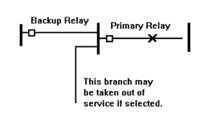
3) Multiply the primary and backup relay currents by the scaling factor. This effectively simulates an intermediate fault in front of the primary relay in which the primary relay current is just below the instantaneous value. See figure below.

Note: This method is exact if the primary relay is on a transmission line that is not mutually coupled. The results are approximate if the line is mutually coupled.
Caution is advised if you plan to use this method for ground relays.
4) Compute the relay operating times.
The above steps are repeated with no outages and then, if selected, with single and double outages of branches that are connected to the primary bus.
OUTLINE OF THE MULTI-POINT COORDINATION CHECKING ALGORITHM:
In contrast to the “classical” method, which checks the primary/backup coordination for a single fault, the multi-point method checks the coordination for a large number of faults along the primary branch, with the remote end of the branch open and closed. Specifically, the multi-point method works like this:
1) The program simulates faults selected by user on the branch where the primary relay group is located: (a) Close-in faults in front of the primary relay group, with the remote end of the branch closed and opened; (b) intermediate faults, with the remote end of the line closed and opened (If the primary group is on a line); (c) Line-end faults; (d) Remote bus faults.
2) In each of faults simulated, the program calculates the operating time of selected relays in the primary and backup groups. The program then calculates the CTI.
3) Depending on the selected report option the program will report the checking result for every fault, or only for faults that result in CTI violations.
4) If the contingency options are tuned on, steps 1 through 3 are repeated with single and/or double outages of branches that are adjacent to the primary relay group.
OUTLINE OF THE RELAY/RECLOSER COORDINATION CHECKING ALGORITHM:
The Relay/Recloser coordination checking logic is designed to detect possible mis-coordination between an upstream relay that backs up a recloser. This algorithm takes into account the relay’s finite reset time, which prevents the relay disk from being reset completely between consecutive recloser operations. If the relay reset time is zero, then this algorithm simply checks the CTI between the recloser curve and the relay curve, for the respective currents. The checking algorithm works as follows:
1) The program simulates close-in faults in front of the recloser with the branch’s remote end opened. This situation is assumed to generate the largest fault currents through the recloser and backup relay. No branch outages are considered.
2) The program simulates the relay’s disk build-up through the sequence of fast and slow operations of the recloser. The report shows the position of the backup relay at the end of this sequence in two ways: (1) As the percent disk travel (100% being the position that causes the contacts to close), and (2) As the time remaining to trip.
3) Step 2 is repeated with the recloser current and the relay current decrease in steps of 10% (of the initial current of step 1) until the recloser stops tripping.
OUTLINE OF COORDINATION CHECKING REPORT:
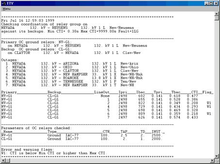
The coordination report heading will include (1) the name of the selected relay group, (2) the CTI criteria, and (3) the fault type.
Following the heading are one or more sections. Each section shows the coordination between a primary relay with one or more backups. At the beginning of each section are the names of primary and backup relays, and a list of branches that will be taken out of service. Each section lists the following:
1) The names of the primary and backup relays that operate fastest in the relay groups.
2) Line outages, if any.
3) The current and operating time of the primary and backup relays.
4) The difference in the two operating times.
5) A warning flag, "W1", if the difference in operating time exceeds Max CTI value or is below the Min CTI value.
Following the last section is a listing of overcurrent relay parameters for those relays checked.
An example coordination report is shown below.

Main Window
CHECK MENU