The OC Minimum Pickup command in the Main Window helps you check the pickup settings of overcurrent ground and phase relays to make sure that they are set low enough to detect faults on the remote-bus and remote line ends. Branch contingencies are automatically considered for the faults on the remote bus. The results are shown in a tabular form. The program flags any case in which the relays’ pickup settings are too low.
Note: There is a newer command for checking relay settings: Check | Relay Settings.
TO CHECK THE PICKUP CURRENT OF OVERCURRENT RELAYS:
1. Optional: Select a relay group if you want to check the relays at the selected group only or if you want to check relays in the vicinity of the selected group.
Click the left mouse button on a relay group.
The selected relay group will turn dotted red.
2. Select the Check | OC Minimum Pickup command.
A dialog box will appear asking you to enter the checking options.

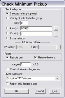
3. Specify the checking extent.
There are five options available. The first two options are grayed and cannot be selected if you did not select a relay group prior to issuing the command.
Selected relay group only: Click on this option to check the relays within the selected relay group only. This option works even if the selected relay group has no relays. In the absence of relays, the report shows only the primary currents at the relay location.
Vicinity of selected relay group: Click on this option and enter a tier limit to check the relays that are in the vicinity of the selected relay group. Set tier to ‘1’ to check relays that are within one bus away, and ‘2’ for relays within two buses away, and so on.
Area(s): Click on this option and enter the area numbers to check the relays within the selected areas. The area string can contain a mixture of ranges and numbers, e.g., “3-5,6,7,10-12”. Press the button “…” on the right if you need help in composing the area string.
Zones(s): Click on this option and enter the zone numbers to check the relays within the selected zones. The zone string can contain a mixture of ranges and numbers, e.g., “3-5,6,7,10-12”. Press the button “…” on the right if you need help in composing the zone string.
Entire network: Click on this option to check all the relays.
Additional criteria – kV range: Enter comma separated list of ranges and discrete values. Each range is defined as lower and upper limits, separated by hyphen ‘-‘ character. Only relay group on buses with nominal kV inside the range(s) will be included in the check.
Additional criteria – Tags: Only relay groups that have the tag string and or are located on bus and line, transformer, phase shifter or switch that has the tag string will be included in the check.
4. Specify checking options.
Click on "Remote bus faults" to check the pickup settings for remote bus faults.
Click on "Remote line-end faults" to check the pickup settings for remote line-end faults.
Click on "Check double contingencies" to consider cases with double branch outages (excluding double transformer outages) in addition to single contingencies.
5. Enter the margin of the pickup setting in "Margin".
The margin must be less than or equal to 1.0. To be considered acceptable, the relay current must be greater than the pickup value divided by this margin. For example, a margin of 0.91 means that the relay currents for the various faults must be at least 10% higher than the pickup.
6. Select where the results will be written.
The choices are either the TTY Window or a report file.
7. Click on “Report only flagged cases” to limit the output to cases with problems.
This option will reduce the amount of output, especially when many relays are being checked.
8. Press OK to begin checking the pickup settings.
The dialog box will disappear and the TTY window will appear showing the program's progress.
OUTLINE OF ALOGORITHM USED TO CHECK PICKUP SETTINGS:
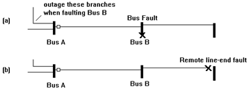
When checking the pickup settings at the relay group as shown in the figure below, the program simulates (a) bus faults at bus B with and without line outages, and (b) line-end faults on branches connected to bus B without outages.

OUTLINE OF REPORT FOR CHECKING PICKUP SETTINGS:
The checking report will appear either on the TTY Window or in a text report file. The sample output for one relay group is shown below. Note that the ground relays are checked with single-line-to-ground faults, and the phase relays are check with 3-phase faults. The tabular output should be self-explanatory, except perhaps for the warning flags, which are explained below:
E3: 'Relay does not trip'. The relay current is too low to trip the relay when it should have.
W3: 'Relay may not pick up'. The relay current is greater than the pickup, but it is smaller than the pickup divided by the margin. Hence, the relay will trip, but not reliably.
E4: 'Instantaneous unit trip'. The relay current is greater than the instantaneous setting. The faults applied should not have tripped the instantaneous unit.
Following the last section is a listing of overcurrent relay parameters for those relays checked.
An example checking report for a single relay group follows.
===============================================================================================
ASPEN OneLiner and Power Flow Version 14.1
Tue Jan 05 15:50:20 2016
Minimum Pickup Checking Report
Checking extent: Selected relay group only:
6 NEVADA 132.kV - 8 REUSENS 132.kV 1 L Nev/Reusens
Margin= 1.000 Number of relay groups checked= 1
-----------------------------------------------------------------------------------------------
Checking minimum pickup of relay group on
6 NEVADA 132.kV - 8 REUSENS 132.kV 1 L Nev/Reusens
____Fault_____Outage__Relay_Name__________Pickup(A)__Current(A)__Time(s)__Flag_
1LG Remote Bus None NV-G1 375.0 3575.8 0.000 E4
1LG Remote Bus 1 NV-G1 375.0 3569.3 0.000 E4
1LG Remote Bus 2 NV-G1 375.0 3013.4 0.000 E4
1LG Remote Bus 3 NV-G1 375.0 3115.5 0.000 E4
1LG Remote Bus 4 NV-G1 375.0 3149.5 0.000 E4
1LG Remote Bus 5 NV-G1 375.0 3213.8 0.000 E4
1LG Remote Bus 6 NV-G1 375.0 3071.4 0.000 E4
1LG Remote Bus 7 NV-G1 375.0 3491.0 0.000 E4
3LG Remote Bus None NV-P1 125.0 3496.5 0.000 E4
3LG Remote Bus 1 NV-P1 125.0 3751.5 0.000 E4
3LG Remote Bus 2 NV-P1 125.0 3020.3 0.000 E4
3LG Remote Bus 3 NV-P1 125.0 3145.5 0.000 E4
3LG Remote Bus 4 NV-P1 125.0 3175.4 0.000 E4
3LG Remote Bus 5 NV-P1 125.0 3175.4 0.000 E4
3LG Remote Bus 6 NV-P1 125.0 2830.9 0.000 E4
3LG Remote Bus 7 NV-P1 125.0 3434.0 0.000 E4
Outage branches:
1. 6 NEVADA 132.kV - 28 ARIZONA 132.kV 1 L Nev/Ariz
2. 6 NEVADA 132.kV - 0 DOT BUS 13.8kV 1 X Nev/NH/Rnk
3. 6 NEVADA 132.kV - 4 TENNESSEE 132.kV 1 P Ten/Nev
4. 6 NEVADA 132.kV - 10 NEW HAMPSHR 33.kV 1 T Nev/NH
-----------------------------------------------------------------------------------------------
Parameters of relays checked:
_OC_Relay_Name_______Type_____________________CTR_____Tap______TD___INST.___Inst_Delay__Reset
NV-G1 Ground IAC-77 100. 2.5 2. 2500 0 0
Main Window
CHECK MENU