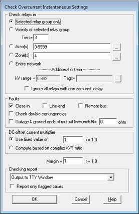
The OC Instantaneous Setting command in the Main Window lets you check the instantaneous settings of overcurrent ground and phase relays to make sure that they are set properly. : Branch outages are considered for the faults on the remote bus. Branch contingencies involving mutually coupled lines automatically consider the case where the outaged line is grounded on both ends. The results are shown in a tabular form. The program flags any case in which the relays’ instantaneous settings are set either too high or too low.
Note: This command does not check overcurrent relay whose instantaneous unit has a non-zero “instantaneous delay.”
Note: There is a newer command for checking relay settings: Check | Relay Settings.
TO CHECK THE INSTANTANEOUS SETTING OF OVERCURRENT RELAYS:
1. Optional: Select a relay group if you want to check the relays at the selected group only or if you want to check relays in the vicinity of the selected group.
Click the left mouse button on a relay group.
The selected relay group will turn dotted red.
2. Select the Check | OC Instantaneous Setting command.
A dialog box will appear asking you to enter the checking options.

3. Specify the checking extent.
There are five options available. The first two options are grayed and cannot be selected if you did not select a relay group prior to issuing the command.
Selected relay group only: Click on this option to check the relays within the selected relay group only. This option works even if the selected relay group has no relays. In the absence of relays, the report shows only the primary currents at the relay location, without any adjustment by the dc-offset multiplier.
Vicinity of selected relay group: Click on this option and enter a tier limit to check the relays that are in the vicinity of the selected relay group. Set tier to ‘1’ to check relays that are within one bus away, and ‘2’ for relays within two buses away, and so on.
Area(s): Click on this option and enter the area numbers to check the relays within the selected areas. The area string can contain a mixture of ranges and numbers, e.g., “3-5,6,7,10-12”. Press the button “…” on the right if you need help in composing the area string.
Zones(s): Click on this option and enter the zone numbers to check the relays within the selected zones. The zone string can contain a mixture of ranges and numbers, e.g., “3-5,6,7,10-12”. Press the button “…” on the right if you need help in composing the zone string.
Entire network: Click on this option to check all the relays.
Additional criteria – kV range: Enter comma separated list of ranges and discrete values. Each range is defined with lower and upper limits, separated by hyphen ‘-‘ character. Only relay group on buses with nominal kV inside the range(s) will be included in the check.
Additional criteria – Tags: Only relay groups that have the tag string and or are located on bus and line, transformer, phase shifter or switch that has the tag string will be included in the check.
Ignore all relays with non-zero inst. delay: Exclude definite time elements from the check.
4. Specify checking options.
Click on “Close-in fault” to check the operating time for close-in faults. The instantaneous unit should trip on a close-in fault.
Click on "Line-end fault" to check the operating time for line-end faults. The instantaneous unit may or may not trip, depending on the protection philosophy.
Click on "Remote bus faults" to check the operating time for remote bus faults. The instantaneous unit should not trip.
Click on "Check double contingencies" to consider cases with double branch outages (excluding double transformer outages) in addition to single contingencies.
5. Select whether you want to program to simulate remote-bus faults with mutually coupled lines outaged and grounded.
If the relays being checked are on a line that is mutually coupled to one or more neighboring lines, the program will simulate additional remote-bus faults with one of these neighboring lines outaged and grounded at a time, unless you unmark this check box. We recommend that you mark this checkbox only if your company has a policy of grounding the outaged lines on both ends.
You can specify a grounding resistance at each end of the outaged and grounded lines.
6. Select dc-offset multiplier options.
The branch currents contain a dc component for a very short time after the onset of a fault. Some relays, either by choice or by design, do not filter out the dc component and, therefore, act on currents that are higher than the symmetric ac fault currents computed by OneLiner. The offset current multiplier allows the checking logic to take the dc offset current into account for relays that are marked as “Sensitive to dc offset” in the relays’ info dialog boxes.
Select “Use fixed value of” and enter a number greater than, or equal to, 1.0 if you want the program to use a fixed multiplier to take into account the effects of the dc offset. Theory tells us that this number can be as large as 1.73.
Select “Compute based on X/R ratio” to have the program calculate dc-offset multiplier value using the complex X/R ratio at the relay location.
7. Enter the instantaneous margin in "Margin".
For the close-in fault, the instantaneous setting is acceptable if the adjusted relay current (of item 5) is less than the instantaneous setting. No margin is used.
For line-end faults, the margin is also not used because no warning messages are issued for line-end faults.
For the other faults (remote-bus fault and remote line-end fault on mutually coupled lines) for which the instantaneous unit should not trip, the instantaneous setting is considered acceptable if it is greater than the adjusted relay current (of item 5) by a margin you enter here. The margin must be 1.0 or larger. For example, a margin of 1.1 means that the instantaneous setting must be at least 10% higher than the adjusted fault current.
8. Select where the results will be written.
The choices are either the TTY Window or a report file.
9. Mark the “Report only flagged cases” checkbox to limit the output to cases with problems.
This option will reduce the amount of output, especially when many relays are being checked.
10. Press OK to begin instantaneous checking.
The dialog box will disappear and the TTY window will appear showing the program's progress.
OUTLINE OF INSTANTANEOUS CHECKING ALGORITHM:
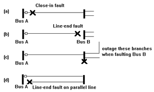
When checking the instantaneous units at
the relay group shown below. 
The program simulates (a) a close-in fault to make sure that the relays trip instantaneously. It then simulates (b) a line-end fault. No warnings are issued for line-end faults because opinion varies on whether the instantaneous should trip. The program simulates (c) remote bus faults with and without outage to make sure that the instantaneous setting is greater than the fault current. If the relays being checked are on a line that is mutually coupled to one or more neighboring lines, the program will simulate additional remote-bus faults with one of these neighboring lines outaged and grounded at a time. (The simulation of the outaged and grounded mutually coupled lines is not shown above.) If the relays being checked are on a line that is mutually coupled to a parallel line, the program also performs (d) a line-end fault on the parallel line to make sure that the relays do not trip instantaneously.
OUTLINE OF REPORT FOR CHECKING INSTANTANEOUS SETTINGS:
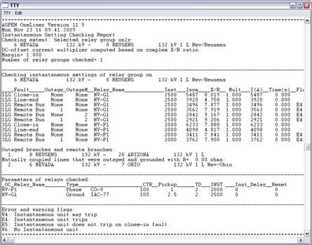
The checking report will appear either on the TTY Window or in a text report file. The sample output for one relay group is shown below. Note that the ground relays are checked with single-line-to-ground faults, and the phase relays are check with 3-phase faults. The tabular output should be self-explanatory, except perhaps for the warning flags, which are explained below:
E5: “Instantaneous unit does not trip on close-in fault”. The relay current, after adjusted for dc offset (if any), is less than the instantaneous setting.
E4: “Instantaneous unit trip”. The relay current, after adjusted for dc offset (if any), is greater than the instantaneous setting, causing the relay to trip when it should not have.
W4: “Instantaneous unit may trip”. The relay current, after adjusted for dc offset (if any), is less than the instantaneous setting, but it is too close to the instantaneous setting to allow for a margin of safety.
W6: “No instantaneous unit”. The relay does not have an instantaneous unit.
Following the last section is a listing of overcurrent relay parameters for those relays checked. An example checking report is shown below.
The column “Outage” shows branches that are outaged. The column “OutageM” shows mutually coupled lines that are outaged and ground on both ends. The column “Mult” shows the actual asymmetric multiplier being used. (The multipliers are all equal to 1.0 in this example because the relays are not sensitive to dc offset.) The rest of the output is self-explanatory.

Main Window
CHECK MENU