The New | Mutual Coupling Pair command in the Main Window lets you specify the zero-sequence mutual coupling between two transmission lines. OneLiner lets you model a pair of lines that are mutually coupled in up to 5 locations without the use of artificial tap buses. To execute this command you must first select the two lines.
TO CREATE A MUTUAL COUPLING PAIR:
1. Select the two lines.
Click the left mouse button once on one of the two lines of the new mutual pair and then with the <Shift> key held down, click the left mouse button once on the second line.
The line symbols will turn dotted red when selected.
2. Select the Network | New | Mutual Coupling Pair command.
Note: This menu item is dimmed and cannot be activated if the lines you selected in Step 1 are already a mutual coupling pair. Use the View | Mutual Pairs on 1-line command to display the mutual pairs identifiers on the 1-line diagram.
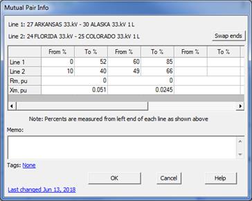
A mutual coupling data dialog box will appear.
The line descriptions are shown above the data grid. The orientation of each line is implied by the order of the end buses as shown in the line description. It’s useful to think of the two end buses of each line as From Bus - To Bus.
The first thing you must do in the next step is to make sure the From-To directions of the two lines are consistent with the way they are in the field. In the example dialog box below, the direction of the line going from Arkansas to Alaska should be the same direction as going from Florida to Colorado. (If that is not the case, press the “Swap ends” button once to make the second line listed as “25 COLORADO 33kV – FLORIDA 33kV 1L”.)

3. Press the Swap ends button if needed to change the From Bus and To Bus of line 2 so that the From-To orientation of the two lines corresponds to the way they are in the field.
Note: The Swap Ends button changes the ordering of end buses for the purpose of specifying the directionality of mutual coupling. It does not alter the parameter Bus1 and Bus2 of line 2.
4. Input the mutual coupling parameters.
From % and To %: Starting and ending point of mutual coupling sections on each line in the pair. Zero percent is at the first end bus of the line, as shown above the data grid.
Note: values of To % of 2nd through 5th mutual segments on line 2 will be computed automatically by the program to match the rest of the To and From% values you have entered.
Rm and Xm: The mutual impedance in per-unit. Base impedance for per unit values is computed as follow:
Zbase = (kV1*kV2) / MVAbase
Where: kV1 and kV2 are nominal kV of the two lines and MVAbase is the system MVA base.
Note: Mutual segments with zero or blank Rm and Xm fields are ignored by the program. See Section 4.8 ZERO-SEQUENCE MUTUAL COUPLING for details on the mutual coupling model.
5. Enter a memo.
The memo is for any notes you wish to keep for this mutual pair. It can have up to 512 characters.
6. Press OK.
The dialog box will disappear and the two lines you selected will remain highlighted.
Main Window
NETWORK MENU