The New | Converter-Interfaced Resource command in the Main Window lets you add a new converter-interfaced resource to a bus. A “converter-interfaced” resource transfers 100% of the power injected or consumed through a converter, or through a back-to-back converter system. Examples of converter-interfaced resources (CIR) include solar plants, type-4 wind plants, and battery energy storage systems (BESS). The control mode is assumed to be Dynamic Reactive Power Control.
The program is designed to simulate CIRs in grid-following operation only. The program assumes that the CIRs are shut down when they are no longer in a network with one or more active conventional generators. An example of such a situation is when a CIR is isolated from the main grid by a branch outage and/or a bus split, and a fault is simulated on a bus within the island.
An experimental feature released in OneLiner Version 15.8 enables the simulation of 3LG faults between a CIR and its POI, even though this fault disconnects the CIR from conventional generators in the network. See the CIR POI 3LG Fault Response Emulation section below for more information.
The symbol of a converter-interfaced resource is a generator with the number ‘4’ inside the circle.

OneLiner’s converter-interfaced resource model has been benchmarked against EPRI/Polytechnique Montreal’s model using an example network. More information is available in the IEEE Technical Report PES-TR78 (see reference below) and information in Appendices K and L of this manual.
The control modes of the converter-interfaced resource is explained in the following.
Dynamic Reactive Current Control
This control mode can be used for just the positive sequence, or it can be used for both the positive sequence and the negative sequence. You can make this selection though the slope parameters of the positive- and negative-sequence controller. By default, the positive sequence slope is 2.0, and the negative-sequence slope is 0.0.
Here is an outline of the solution method.
Note: We use the convention wherein current is positive if it is being injected to the network by the device.
Phase One
The program does the following in the first 10 iterations:
•It injects a + sequence dynamic reactive current to the positive-sequence network, based on the magnitude of (1.0 –v1), the + sequence slope, and the power-factor angle, where v1 is the + sequence voltage.
•At the same time, it injects a negative sequence current in the -sequence network, based on the magnitude of v2 and the -sequence slope, at an angle 90 degrees ahead of the v2 phasor, where v2 is the negative sequence voltage.
•The magnitude of the + sequence dynamic reactive currents is limited to the current limit specified by the user (e.g., 1.2 times full load current).
•The magnitude of the -sequence dynamic reactive currents is limited to the full load current.
•At the end of this phase one, a floating-point scalar alpha is initialized to 1.0.
Phase Two
•At the 11th and subsequent iterations, the program computes the dynamic reactive currents the same way as in phase one. It then scales both the + sequence reactive current and the –sequence reactive current by the scalar alpha.
•The scaled reactive current phasors are converted to the phase domain.
•If the maximum phase current is smaller than the current limit, and the + sequence voltage magnitude and power-factor angle have settled into a narrow range, then we have convergence.
•Update alpha with this equation: alpha = (current limit) / (max phase current) and perform another phase-two iteration.
Converter-interfaced resources inject no zero-sequence current because (a) converter-interfaced resources are usually connected line-to-line, and (b) the unit wye-delta transformer is connected with the delta winding on the collection-network side – thus blocking any zero-sequence current flow.
Iterations are required to model converter-interfaced resources due to the non-linear nature of the device. Before simulating faults, you must turn on the “Simulate converter-interfaced resources” option in the Fault | Options dialog box.
The prefault voltage option must be set to “From a linear network solution” or “From a power flow solution”. The second option is available only if you have a license for the ASPEN Power Flow Program. Converter-interfaced resources cannot be simulated in v15 if the prefault voltage option is set to “Assume flat”.
If you are using the prefault voltage option of “From a linear network solution”, we suggest you set the Unit MW Generation parameter to zero if there are no loads in the network, in keeping with the traditional treatment of synchronous machines in short circuit studies. More details on this topic are in Appendix K.
We encourage you to aggregate your converter-interfaced resources as much as possible. Aggregation will speed up fault simulations and eliminate unwanted numeric oscillation between clusters of closely spaced converter-interfaced resources during the iterative solution.
Appendix L has more information on converter-interfaced resources, in a Question-and-Answer format. For more information, please see references below.
TO ADD A NEW CONVERTER-INTERFACED RESOURCE FROM THE DEVICE PALETTE:
1a. Click on the New Converter-Interfaced Resource button  on the Device Palette. The cursor will become a cross with a
converter-interfaced-resource symbol attached to it.
2a. Click on the one-line where you want to place the new resource.
Note: You can click on an existing bus to place the new converter-interfaced resource on the bus. The bus cannot have any one of the following object already: a converter-interfaced resource, a generator (with or without current limit), a voltage-controlled current source, or a type-3 wind plant.
TO ADD A NEW CONVERTER-INTERFACED RESOURCE TO A BUS USING MENU COMMAND:
1b. Select the bus.
Click the left mouse button once on the bus to which you want to add a converter-interfaced resource.
The bus symbol will turn dotted red when selected.
2b. Select the Network | New | Converter-Interfaced Resource command.
Note: This menu item is dimmed and cannot be activated if the bus you selected already has a converter-interfaced resource, a generator (with or without current limit), a voltage-controlled current source, or a type-3 wind plant.
A dialog box will appear asking for the converter-interfaced resource data.

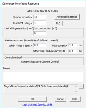
1. Specify the number of units in this plant.
2. Specify the unit MVA rating.
3. Enter the unit MW generation.
If the prefault voltage option is set to “From a power flow”, enter the real power the wind plant is generating before the fault. This value must be positive or zero.
If the prefault voltage option is “From a linear network solution”, we suggest you enter the value of 0 if there are no loads in the network. This will make it consistent with the classical treatment of conventional synchronous generators in short circuit programs. See Appendix K for a discussion of this topic.
4. Specify the maximum current output.
The maximum current is usually somewhere between 1 to 2 times the full-load current. You may find in your converter data sheet that the maximum current varies as a function of the “time since fault inception”. In that case we suggest you use the value at 2 to 3 cycles.
The largest value you can enter is 3, which is need for the simulation of some STACOM devices.
You can optionally reduce the maximum current to a lower value when the voltage is low, using the parameters within the “Maximum current (in multiple of full-load current)” group box. The values in the above dialog box sets to the maximum current to 1.1 times full load current when the terminal voltage is above 0.5 pu, and reduces the maximum current to 0.4 times full load current at lower voltages.
5. FLC
Press this button to see the full-load current of the converter-interfaced resource.
Click on the … button near the upper right corner of the text area below the Memo field to open the Supplemental Object Properties dialog box with a data grid to enter data for the following data fields:
6. In/Out of service date: Click on the … button and enter the desired dates. See the Details and Techniques section “In/Out of service and tags” for more information.
7. Tags: Enter list of tag strings separated by semicolon. The tags are for organizing objects that are related for some purpose. Please see documentation for Network | Apply Tag for more information.
8. User-defined fields: These are custom data fields that are defined by the user. Please see documentation for File | Preferences for information about how to specify the template for these data fields.
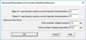
Press the Advanced Settings button to bring up this dialog box.

1. Slope of the positive-sequence reactive injection characteristics.
This value must be in the range [1.0, 30.0]. Typical value for a solar or type-4 wind plant is between 1.0 and 2.0. The default is 2.0. The upper limit of 30 is needed for some STACOM devices. See Appendix L for the method to estimate the slope.
2. Slope of the negative-sequence reactive injection characteristics.
The default is 0, which means the converter does not inject reactive current in the negative sequence. To enable the injection of negative-sequence reactive current, enter a positive number for the slope of the negative-sequence reactive current characteristics. This slope, if not zero, must in the range [0.5, 30.0]. The value of 2.0 is recommended by the German grid code for solar and wind plants. The upper limit of 30 is needed for some STATCOM devices. .In any case, we recommend you set this slope no higher than the positive-sequence slope.
Note: The majority of converters in the US at the time of this writing (year 2021), do not inject negative-sequence reactive current. But we expect this to change in the near future.
3. Terminal voltage limits.
The converter-interfaced resource will shut down if a phase voltage exceeds the upper limit, or it goes below the lower limit. The lower limit can be as low as 0.0 per-unit.
Note: When entering the terminal-voltage limits for wind, solar and similar devices, we advise users to consult IEEE Standard 2800 and other relevant standards on voltage ride-through parameters. If you enter a value of zero for the low-voltage shutdown, please keep in mind that the CIR can output current for a very brief period before it shuts down.
4. Press OK to close the Advanced Settings dialog box.
Press the OK button in the main info dialog box when done. A new converter-interfaced resource will be added to the bus.
CIR POI 3LG Fault Response Emulation
To support requests from many users, an experimental feature has been added to allow the simulation of bolted 3LG faults between a converter-interfaced resource (CIR) model and its point of interconnection (POI) to the network.
The feature is labeled as “experimental” because the phasor-domain behavior of CIR in response to this fault condition is still in the research stage. While the pre-fault memorization techniques employed in this experimental feature may be possible, it is unclear whether this technique reasonably replicates the expected performance of actual IBR and associated control systems.
ASPEN recommends caution when using this experimental functionality, and each simulation result should be scrutinized.
ASPEN appreciates feedback from users who experiment with this feature. Please send questions or comments to support@aspeninc.com.
The POI Fault Emulation is based on two assumptions:
Assumption 1: The CIR's phase-locked-loop (PLL) memorizes the pre-fault voltage angle. This memorized angle becomes the reference for the IBR output current. In OneLiner, a pre-fault network voltage solution is calculated as an initial step before calculating the faulted network solution. Upon addition of the fault to the network, if a CIR POI voltage magnitude becomes zero, the memorized pre-fault voltage angle will be used.
Assumption 2: The CIR aims to output current with a power factor angle of negative 90 degrees (voltage angle minus current angle equals -90) but is restricted to the power factor angle of the impedance between the CIR and the 3LG POI fault. Therefore, the phase angle of the CIR output current relative to the memorized voltage angle will match that of the circuit between the CIR and the POI fault. This condition is detected in OneLiner when the power factor angle does not change during the first two iterations of the fault solution.
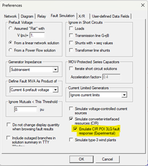
The experimental POI Fault emulation is disabled by default but can be enabled in the Fault Options menu, as highlighted below.

Reference:
IEEE Power & Energy Society Technical Report PES-TR78 “Modification of Commercial Fault Calculation Programs for Wind Generators” June 2020
IEEE Standards Association, 2800 – Standard for Interconnection and Interoperability of Inverter-Based Resources Interconnecting with Associated Transmission Electric Power Systems, 2022.
Main Window
NETWORK MENU