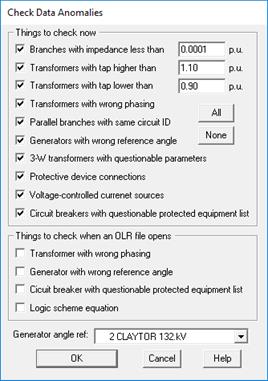
The Network Anomalies command in the Main Window looks for anomalies in the network data and reports its findings in the TTY Window. The user can also direct the program to automatically check for anomalies each time when a binary file is opened.
TO CHECK FOR NETWORK ANOMALIES:
1. Select the Check | Network Anomalies command.
A dialog box will appear asking you to select which network anomalies to check.

2. Mark "Branch with impedance less than" and enter a threshold value (in per unit) to look for branches with impedances smaller than the threshold.
Branches with very small impedance can cause numerical problems and result in grossly incorrect short circuit solutions. The smallest impedance one can use for lines and transformers is a function of the system being modeled. In most networks, branch impedances that are 0.001 per-unit or larger do not cause problems.
3. Mark "Transformer tap too high" and enter a threshold value (in per unit) to look for transformers with unusually high tap ratios.
Click on "Transformer tap too low" and enter a threshold value (in per unit) to look for transformers with unusually low tap ratios.
The program will list any 2- or 3-winding transformers whose tap KVs are outside of the “normal” range you specified.
4. Mark "Transformer with wrong phasing" to look for 2- and 3-winding transformers with incorrect phase shift.
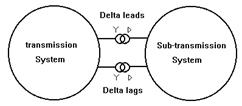
An example of a system with wrong phasing is shown below. Here, the sub-transmission system is connected to the transmission system though two wye-delta transformers, one with the delta leading and the other with the delta lagging.
Phasing errors in practice are rarely this obvious. The program logic is capable of finding them nonetheless.
Note: The program will check only the transformers that are in the same contiguous network as the generator being shown in the “Generator Angle Ref” drop-down list box.

5. Mark "Parallel branches with same circuit ID" to look for parallel transmission lines and transformers that have the same circuit ID.
Parallel lines must have different circuit IDs so that the program can tell them apart. The same is true with transformers, phase shifters, switches and other branch types.
Two 3-winding transformers are considered in parallel when they share the same primary and secondary bus terminals.
6. Mark “Generators with wrong reference angle” to look for generators whose reference angles are inconsistent with the phase shift of the network elements.
Perform this check only if you are using the “from a linear network solution” starting option for short circuit simulations. See documentation of the Fault Simulation tab of the File | Preferences command and 4.9 for more information on prefault voltage profile.
Select a generator in the “Generator Angle Ref” drop-down list box below. The program will use this generator’s angle as the reference and temporarily compute the reference angle of all the other generators in the same contiguous network. The program will then compare the computed reference angle to the reference angle in the generators’ info dialog boxes. It will report on any differences found.
Note: The generator’s reference angles are not changed by this command. If you want the program to set the generator reference angle automatically, see the Network | Set Generator Ref Angle command.
Note: The program will check only the generators that are in the same contiguous network as the generator being shown in the “Generator Angle Ref” drop-down list box. The program will also automatically omit fictitious generators that were created by the Boundary Equivalent command.
7. Mark “3-W transformers with questionable parameters” to look for 3-winding transformers with dubious short-circuit impedances or winding configurations. Specifically, the program will report on wye-wye-delta transformers with Zpso greater than, or equal to, Zps. Normally, Zpso should be smaller than Zps.
8. Mark “Logic scheme equation” to make sure all logic schemes have valid logic equations.
The program will make sure that all the variables are defined, the equations have limited number of terms, and there are no circular references.
9. Mark “Voltage-controlled current sources” to check for large abrupt changes within the table of voltage, current and power-factor angle, which can negatively affect the numerical solution convergence.
NOTE: The numerical solution convergence can be affected by other factors, such as the relative short circuit strength between the VCCS and the rest of the system or the number of non-linear elements in the network. Therefore this checking report may include VCCSs with abrupt changes in the data, which the program still successfully solves with within acceptable convergence tolerance.
10. Mark “Circuit breakers with questionable protected equipment list” to look for circuit breakers with either (1) no protected equipment, (2) protected equipment that is out of service, and (3) protected equipment that is not connected to the same bus as the circuit breaker.
11. Select “Things to check when an OLR file opens”.
Mark one or more of the three checkboxes available if you want the program to perform the network-anomalies checks automatically whenever it opens an OLR file.
The program will show a message box when it detects any anomalies. The details will be available in the TTY Window.
12. Press OK to close the dialog box.
Anomaly checking will commence if you have marked one or more items in the “Things to check now” group box.
The program will look for all of the anomalies you selected above and output the result to the TTY Window. If there are any anomalies, you must correct them manually.
Close the TTY window when you are done.
Main Window
CHECK MENU