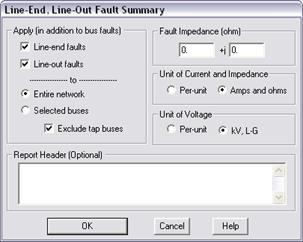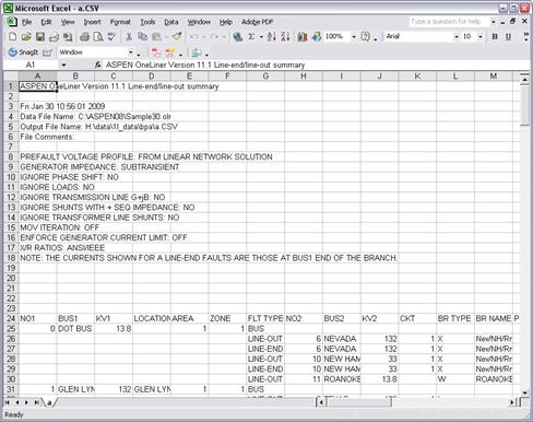
The Line-End/Out Fault Summary Command in the Main Window lets you create a table with fault current and X/R ratio for a number of buses under line-end and line-out conditionsThe results are written in a tabular form to a CSV-formatted file that can be opened by any spreadsheet programs.
TO CREATE A LINE-END/OUT FAULT SUMMARY:
1. Select the Fault | Line-End/Out Fault Summary command.
A dialog box will appear asking you to specify the faults.

2. Select the fault types.
Click on Line-end faults to apply a fault at the remote end of each of the branches incident on the bus with the far end of the branch disconnected.
Click on Line-out faults to apply a fault at the bus with each of the branches incident on the bus taken out of service one at a time.
A bus fault is always included.
3. Select the buses to be faulted: “Entire network” or “Selected buses”.
If you selected “Selected buses”, the program will ask you to select the buses later.
4. Mark the check box ‘Exclude tap buses’ to omit line-end and line-out fault on tap buses.
5. Enter the fault impedance in 'Fault Z (ohm)'.
6. Select units of output.
In the “Unit of current and impedance” group box, press the "p.u." radio button to display currents and impedances in per unit, or the “Amps and ohms” radio button to display currents and impedances in physical units.
In the “Unit of Voltage” group box, press the "p.u." radio button to display bus voltages in per unit, or the “kV, L-G” radio button to display voltages in kV, line-to-ground.
7. Enter header text for the fault summary report. This text will be shown at the beginning of the report file.
8. Press OK to create the line-end and line-out fault summary.
If you elected to fault selected bus, the Bus selector dialog will appear.
Use the bus selector controls to build a list of buses that you want to include in the fault summary. See APPENDIX H: BUS SELECTOR for more information on the Bus Selector. Click OK when done.
A File Save dialog will appear.
Use the standard controls in the dialog to specify name and location of the CSV-formatted output file.
Click on Save when done. The program will create the output file at the location specified. As information dialog box will appear when the output file is complete.

Click on Yes to view the fault summary.

Bus fault summary file data fields are:
NO1, BUS1, KV1: Identifier of Bus1. This is the faulted bus for bus faults and line-out faults.
LOCATION, Area, Zone: Bus1’s location, and area and zone number.
FLT TYPE: ‘BUS’ for bus fault; ‘LINE-OUT’ for line-out fault; ‘LINE-END’ for line-end fault.
NO2, BUS2, KV2: Identifier of the end bus (Bus2) for line-end and line-out faults. A line-end fault is applied to the Bus2 end of the branch after it has been discounted.
CKT, BRTYPE: Circuit ID and branch type for the branch between Bus1 and Bus2, for line-end and line-out faults.
3LG Phase(A), Gnd(A), X/R: 3-phase fault currents in amps and X/R ratio.
2LG Phase(A), Gnd(A), X/R: 2-line-to-ground fault currents in amps and X/R ratio. : ground current
1LG Phase(A), Gnd(A), X/R: single-line-to-ground fault currents in amps and X/R ratio.
L-L Phase(A), Gnd(A), X/R: line-to-line fault currents in amps and X/R ratio.
Max Phase(A): Maximum phase current among all the faults on this bus.
Max Gnd(A): Maximum ground current among all the faults on this bus.
Z+, Z-, Z0: Positive-, negative- and zero-sequence Thevenin impedances in ohms.
SCFLAG_3LG, SCFLAG_2LG, SCFLAG_1LG, SCFLAG_LL: Lists of MOV-protection of series capacitors that operated in each of four faults on this bus.
Note: The X/R ratios in the report are either ANSI/IEEE X/R ratios or complex X/R ratios, depending on the option you selected in the Fault | X/R Ratios command.
The columns for series capacitors are not shown if the MOV iteration is not turned on in the Fault Simulation tab of the File | Preferences dialog box.
All three terminals of a 3-winding transformer are disconnected when the transformer is outaged.
The currents reported for a line-end fault are those measured at the unfaulted end of the branch. It may not equal the total fault current if there are shunts on the branch.
Main Window
FAULTS MENU