The IEEE 1584-2018 Arc-Flash Hazard Calculator Command in the Main Window lets you perform arc-flash hazard calculation using the methodology recommended in the IEEE 1584-2018 standard. OneLiner automatically simulates a 3-phase fault at selected bus to determine arcing current and fault clearing time. The program utilizes IEEE 1584-2018 curve fitting equations in the calculation of arcing currents, incident energy, and arc-flash boundary.
NOTE: The IEEE 1584-2018 Arc-Flash Hazard Calculator Command will not run on buses with nominal kV above 15 because this kV level is outside the range of the empirically derived model in the standard.
TO RUN THE ARC-FLASH CALCULATOR:
1. Select the Fault | IEEE 1584-2018 Arc-Flash Hazard Calculator command.
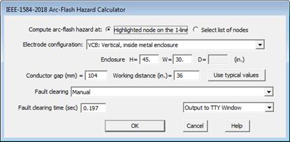
A dialog box will appear asking you for the calculation parameters.

2. Select the study extent: Highlighted node on the 1-line or Select list of nodes
If the second option is selected the program will display the Node Selector dialog (see Error! Reference source not found.) to let you build the list before commencing the calculation.
3. Select electrode configuration:
Click on the dropdown list to select one of the following IEEE 1584-2018 electrode configurations for equipment at the site under study:
•VCB: Vertical conductors/electrodes inside a metal box/enclosure
•VCBB: Vertical conductors/electrodes terminated in an insulating barrier inside a metal box/enclosure
•HCB: Horizontal conductors/electrodes inside a metal box/enclosure
•VOA: Vertical conductors/electrodes in open air
•HOA: Horizontal conductors/electrodes in open air
For VCB, VCBB and HCB configurations only: Enter equipment enclosure dimensions.
NOTE: Enclosure depth is required only when calculation is being performed at bus with nominal kV of 0.6kV or lower.
Enter conductor gap in millimeters. This is the gap over which arcing takes place.
Enter working distance. This is distance from the possible arc point to the person.
Click on Use typical values button if you want to use values for conductor gap, working distance and enclosure dimensions for different equipment class at selected kV per IEEE 1584-2018 Table 8.
4. Click on the dropdown list labeled Fault clearing to specify the method for determining fault clearing time for 3-phase fault at this site.
Choose Manual if you want to enter the fault clearing time manually.
Choose Stepped-event simulation if you want the program to determine the clearing time from stepped-event simulation with the initiating event being a 3LG fault at the selected node.
Choose Fastest device in the list below or select a specific device in the list if you want to use the operating time of nearby protective devices in the vicinity. Following logic is utilized in clearing time calculation:
•Only phase relays, reclosers and fuses operation is considered.
•If the device is a fuse, the total clear time curve is used. If the device is a recloser that has two tripping curves, the fast curve is used.
•If the tripping device is not a fuse, total arc clearing time calculated as the sum of device tripping time and breaker interrupting time.
5. (Only if Manual is selected in step 4) Enter fault clearing time in seconds.
7. Select in the dropdown list the options of Output to TTY window or Output to Excel CSV file.
8. Press OK to start calculation.
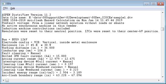
Arc-flash hazard report will be printed in the TTY window or in CSV file as you selected.

Main Window
FAULTS MENU