The Arc-Flash Hazard Calculator command in the Main Window performs arc-flash hazard calculation according to the IEEE 1584-2011 standard. You can use this command to do the calculation for just one bus, or for a collection of buses.
For each bus, OneLiner automatically simulates a 3-phase bus fault to determine the arcing current. You can choose one of several ways of computing the fault clearing time.
OneLiner employs the IEEE 1584-2011 curve fitting equations to calculate the arcing current and the incident energy when bus nominal kV is 15 or less. The program employs the Lee-method equations in all other cases, as recommended by IEEE 1584-2011.
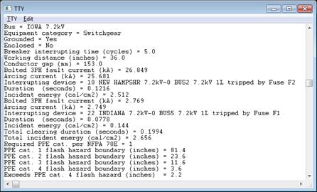
The report generated by this command shows the arc-flash incidence energy for arc at 100% and also at 85% of the total 3-phase fault current. The report also shows the minimum category of PPE (personal protective equipment) at working distance per NFPA 70E. The report also gives the arc-flash hazard boundaries for different categories of PPE.
TO RUN THE ARC-FLASH HAZARD CALCULATOR FOR ONE BUS:
1a. Highlight the bus by clicking the mouse button on it.
Select the Faults | IEEE 1584-2011 Arc-Flash Hazard Calculator command.
Go to step 2.
TO RUN THE ARC-FLASH HAZARD CALCULATOR FOR MULTIPLE BUSES:
1b. Make sure no bus is selected.
Select the Faults | IEEE 1584-2011 Arc-Flash Hazard Calculator command.
The Bus Selector will appear to let you specify the buses at which the arc-flash hazard calculation will be perform.
Use the bus selector controls to build a list of buses. See APPENDIX H: BUS SELECTOR for more information on the Bus Selector. Press OK when done.
2. Enter calculation parameters.
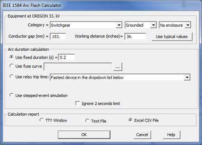
A dialog box will appear asking you for the calculation parameters.

3. Select an equipment category:
Click on the dropdown list to select one of the following IEEE 1584 equipment type at the site under study:
•Switch gear
•Cable
•Open air
•MCC and panel boards (available only for buses of 1 kV or lower)
Click on the dropdown list to select whether the system is grounded or ungrounded.
Click on the dropdown list to select whether the equipment has no enclosure or it is inside an enclosed box.
Enter conductor gap in millimeters. This is the gap over which the arcing takes place.
Enter working distance in inches. This is distance from the possible arc point to the person.
Click on Use typical values button if you want to use commonly used values for conductor gap, working distance and enclosure type for the selected equipment category and kV level.
4. Choose one of four methods for calculation the time required to clear the 3-phase fault.
Click on the radio button Use fixed duration if you want the program to use the fault clearing time you specify.
Click on the radio button Use fuse curve if you want the program to use the fault clearing time you specify.
Click on the radio button Use relay trip time if you want the program to use the operating time of a protective device.
Click on the radio button Stepped-event simulation if you want the program to calculate the fault clearing time for the bus fault using stepped-event simulation.
5. Enter the necessary data, depending on the method you selected in the last step.
A: USE FIX DURATION
Enter the total fault clearing time in seconds.
B: USE FUSE CURVE
Click on the button labeled “…” and use the Curve Selector to select a fuse curve for calculating the fault clearing time.
C1: USE RELAY TRIP TIME FOR A SINGLE-BUS RUN
Choose “Fastest device in the list below” if you want the program to use the fastest operating time among the protective devices in the vicinity of the selected bus.
Note: The program assumes the fault is cleared by a single protective device. In cases when two or more devices must trip to completely clear the fault, OneLiner is likely to use a clearing time that is too short, which leads to an arc-flash calculation that is not sufficiently conservative. We suggest you use the “Stepped-event simulation” option instead.
Alternatively, choose a protective device in the drop-down combo box if you want the program to use the fault clearing time of that device.
Enter the breaker interrupting time in seconds. This is the time it takes for the circuit breaker to interrupt the fault current, after it receives the trip signal.
C2: USE RELAY TRIP TIME FOR A BATCH RUN
The words “Fastest device in vicinity” will appear in the drop-down combo box, meaning that the program will use the fastest operating time among the protective devices in the vicinity of the bus being studied. You will not be able to change this selection.
Enter the breaker interrupting time in seconds. This is the time it takes for the circuit breaker to interrupt the fault current, after it receives the trip signal.
The following logic is utilized to calculate the fault clearing time:
•Only the operations of phase overcurrent and distance relays, reclosers and fuses are considered.
•If the device is a fuse, the total-clear time curve is used. If the device is a recloser that has two tripping curves, the fast curve is used.
•If the tripping device is not a fuse, the total arc clearing time is calculated as the sum of device tripping time and the breaker interrupting time.
D: STEPPED-EVENT SIMULATION
Enter the study extent in tiers.
The program will perform a stepped-event simulation with initiating event of a 3-phase fault at selected bus within the study extent you entered here and the “Protective devices considered” of the Stepped Event Analysis command. Results of sequence of protective device operations, associative fault current and time duration are used in the arc flash hazard calculation. A stepped-event simulation will be performed
6. Mark the Ignore 2 seconds limit to permit the use of fault clearing time of greater than 2 seconds in the calculation of the arc flash results.
The maximum fault clearing time of 2 seconds is stipulated in the IEEE 1584 standard. The program ignores this rule if you mark this check box.
Note: The “2 seconds limit” will always apply in the cases when fault is not cleared by protective devices.
7. Select report option: To TTY Window, to a text file, or to a CSV file that can be viewed or edited in any spreadsheet program.
8. Press OK to start calculation.
The program will simulate a 3-phase fault on the selected bus to determine the bolted fault current.
Arcing current and incident energy are computed using an IEEE 1584 model that matches the selected bus nominal kV level. Incident energy is calculated at 100% and 85% of total arcing current according to the standard requirements except when arc duration calculation of stepped-event simulation is selected. The program does not perform 85% current calculation when this option is selected.
Arc-flash hazard report will be shown in the TTY window or saved in disk file according to the report option you had selected.

Note: “PPE cat. x flash hazard boundary” defines the area, inside which PPE category x or higher is required per NFPA 70E.
Main Window
FAULTS MENU