The Ground Current Calculator command in the Main Window helps you tabulate and total the ground currents from transformer neutrals, loads, and shunts at a number of buses you specify. This information may be useful in studies involving step and touch potential and substation grounding-mat design. You must simulate one or more faults before executing this command.
TO CALCULATE THE TOTAL GROUND CURRENT:
1. Simulate one or more faults on, or in the vicinity of, a ground mat.
2. Select the Faults | Ground Current Calculator.
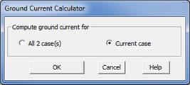
This dialog box will appear only if more than one fault solutions are available. The absence of this dialog box means the ground current will be calculated for the fault solution that is being displayed.

Click on the Current case radio button to show the ground currents for the fault solution being displayed on the one-line dialog.
Otherwise, click on the All xx case(s) radio button to show the ground currents for all the faults that you have simulated. (xx is the total number of faults.)
Press OK.
3. The bus selector dialog box will appear. Use the bus selector to select buses that share the same grounding mat. See APPENDIX H: BUS SELECTOR for more information on the Bus Selector. Press OK when done. In the following, we will refer to this as the “bus list”.
4. Specify the output file name.
The ground current report will be saved in a CSV file. A File Save dialog will appear.
Use standard controls in the dialog to specify name and location of output file.
Press Save to create the ground-current report file.
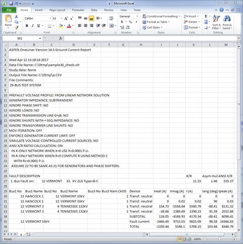
OneLiner will ask you if you want to see the results using your spreadsheet program. If you answer ‘yes’, you will see a window that looks like this.
The beginning of the report shows a time stamp and documents the fault-solution options.

The results for each fault begin with the fault description and the X/R ratios and the value of the asymmetric multiplier.
The ground current includes all the neutral currents of transformer (2- or 3-winding) if one of the terminal buses of the transformer is in the bus list. The program automatically adds the other terminal buses to the bus list, if they are not already there. The underlying assumption is that if one terminal of a transformer is on the ground mat, the other terminals of the transformer are also on the same ground mat.
The ground current also includes the neutral currents of shunts, grounding banks, loads and generators that are attached to any of the buses in the list.
If one of the buses in the bus list were faulted, the program will first show the ground current calculated thus far under the heading of “SUBTOTAL”. The sum of zero-sequence fault currents is shown immediately below, under “Fault current”. Finally, the total ground current, which is the sum of neutral currents and fault currents, is shown under the heading of TOTAL. To put it another way, the amount under TOTAL is the ground current when the faults are on the grounding mat, and the amount under SUBTOTAL is the ground current when the fault is just outside the ground mat.
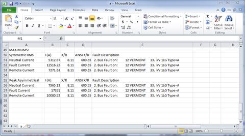
A summary of the symmetric currents and asymmetric currents are shown at the end of the report if more than multiple faults are included. The summary looks like this:

The meaning of “Neutral Current” and “Fault Current” should be self-explanatory. The “Remote Current” is amount under “TOTAL” for the individual faults.
Main Window
FAULTS MENU