The PRC-25-1 Standard was created in response to a number of expected generator trips during the 2003 blackout when the voltage in the transmission network dropped to as low as 0.85 per-unit. A detailed analysis revealed that prior to tripping, these generators were generating near their MW limit, while supplying VARs as high as 1.5 times the numerical value of the their rated MW – due to a controlled response called “field-forcing”. This transient condition apparently confused some phase relays near the generators to conclude erroneously that the generators were feeding into a fault. PRC-025-1 provides guidelines for setting relays at and near generators to prevent a recurrence.
The Add | Generator Loadability Limit command in the DS Relays Window computes and draws the generator loadability limit in the form of a slanted dotted line on the R-X diagram. The PRC-25-1 Standard requires the maximum torque angle of the phase distance relay to not go beyond this dotted line.
Note: The PRC-25-1 Standard is lengthy and complex. This command addresses only a subset of the Standard’s requirements. The user should consult the text of the Standard for details.
TO DISPLAY THE GENERATOR LOADABILITY LIMIT:
1. Select the Add | Generator Loadability Limit command.
Note: This command is dimmed and cannot be execute if a generator loadability curve is already being displayed. To add a new loadability curve, you must first delete the existing curve with the Delete | Generator Loadability Limit command.
Note: This command is also dimmed if the first relay in the DS Relays Window is not a phase relay or that the relay is not on a transmission line or transformer.
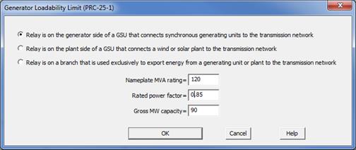
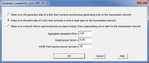
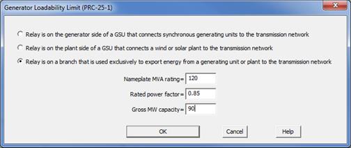
A dialog box will appear. The three input parameters vary depending on which of the three radio buttons is highlighted.
CASE 1: RELAY IS AT THE GENERATOR SIDE OF A 2-WINDING STEP-UP TRANSFORMER THAT CONNECTS THE GENERATING UNIT(S) TO THE NETWORK. THE RELAY CAN ALSO BE ON THE GENERATOR SIDE OF A 3-WINDING DUAL-SECONDARY GSU.
Note: This radio button is dimmed if the first relay on the DS Relays Window is not on the low side of a 2- or 3-winding GSU transformer.

Nameplate MVA rating: Nameplate MVA rating of the generating unit(s). In the case of a dual-secondary GSU, enter the rating of one of the two identical generators.
Rated power factor: Rated power factor of the generating unit(s)
Gross MW capacity: Gross MW capability of the generating units, as reported to the Transmission Planner. In the case of a dual-secondary GSU, enter the capacity of one of the two identical generators.
The method we use for this case is called “option 1b” in the Standard, which applies to phase relays (21) on the generator-side of the GSU looking toward the network. The MW output of the unit(s) is assumed to be equal to the gross MW capacity. The MVAR output is assumed be equal to 1.5 times the numerical value, derived from multiplying the nameplate MVA rating and the rated power factor.
The network-side voltage of the GSU is fixed at 0.85pu. The plant-side voltage is calculated from an iterative solution of the power-flow equation, which takes into account the turns ratio and impedance of the GSU.
The limiting impedance is calculated as 115% of the impedance based on the low-side voltage and the MW+jMVAR output of the unit(s). OneLiner draws a black dot at the location of the limiting impedance. The dotted line shown on the R-X diagram is perpendicular to this limiting-impedance vector.
CASE 2: RELAY IS ON THE PLANT SIDE OF A GSU THAT CONNECTS A WIND/SOLAR PLANT TO THE NETWORK
Note: This radio button is dimmed if the first relay on the DS Relays Window is not on the low side of a 2-winding GSU transformer and it is not on the wye-winding of a 3-winding transformer.

Aggregate nameplate MVA: The maximum aggregate nameplate MVA output from all the units within the plant.
Rated power factor: Rated power factor of the units.
MVAR from reactive power devices: Total static compensation in MVAR. Enter a positive value for capacitive MVARS, and negative for reactive MVARS.
The method we use for this case is called “option 10” in the Standard, which applies to phase relays (21) on a GSU that connects “asynchronous generators only (including inverter-based installation)” to the network. Most MW-size wind and solar plants fit this description. Again, the phase relays are on the plant side of the GSU looking toward the network.
The MW+jMVAR output of the plant is computed based on the aggregate nameplate MVA and the rated power factor. The MVAR from reactive power devices is added to the MVAR output.
The network-side voltage of the GSU is fixed at 1.0 per-unit. The plant-side voltage is estimated using the transformer turns ratio alone.
The impedance limit is calculated as 130% of the impedance derived from the net MW+jMVAR output from the plant and the GSU’s low-side voltage. The dotted line shown on the R-X diagram is perpendicular to this limiting-impedance vector.
CASE 3: RELAY ON A BRANCH THAT IS USED EXCLUSIVELY TO CONNECT THE GSU TO THE NETWORK
Note: This radio button is dimmed if the first relay on the DS Relays Window is not on a line and it is not on a 2- or 3-winding transformer.

Nameplate MVA rating: Nameplate MVA rating of the generating unit(s).
Rated power factor: Rated power factor of the generating unit(s)
Gross MW capacity: Gross MW capability of the generating units, as reported to the Transmission Planner.
The method we use for this case is called “option 14a” in the Standard, which is most commonly used for:
•Phase relays (21) on the high side of the GSU, looking “backwards” toward the network, or
•Phase relays (21) on a transmission line that is used exclusively to connect the GSU to the network. The Standard applies only to relays on the line that look toward the network, and NOT to the ones that look toward the GSU.
The MW output of the unit(s) is assumed to be equal to the gross MW capacity. The MVAR output is assumed to be equal to 1.2 times the numerical value computed from multiplying the nameplate MVA rating by the rated power factor.
The voltage at the network side of the GSU is assumed to be 0.85 per-unit.
The limiting impedance is calculated as 115% of the impedance based on the 0.85 per-unit voltage and the MW+jMVAR output of the unit(s). The dotted line shown on the R-X diagram is perpendicular to this limiting-impedance vector.
2. Press OK to show the PRC-025-1 limit.
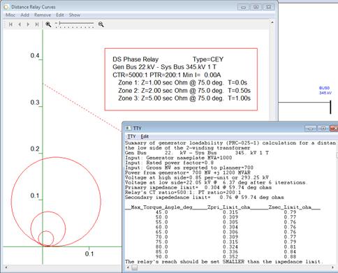
A dotted line should appear on the R-X diagram. The calculations and the coordinates of the dotted curves are documented in text in the TTY Window.
If you cannot see the dotted line, open the TTY Window and take a look at the coordinates of the points for this line. You may have to zoom in if the limiting impedance is very small, or zoom out if it is large.
A sample diagram is shown below.

DS Relays Window
ADD MENU