The Fault Locator command in the Main Window helps you locate a fault on a transmission line given the voltages and currents that were recorded at one or both ends of the line when the fault took place. This command works by simulating intermediate faults along the faulted line with various amounts of fault resistance and compares the result apparent impedance to fault in each case to the values calculated from the recorded relay voltages and currents in actual fault event to produce a report with the best-matched cases. The apparent fault impedance calculation is carried out using impedance-base fault location algorithms described in this reference: [S. DAS, S. SANTOSO, A. GAIKWAD and M. PATEL, “Impedance-Based Fault Location in Transmission Networks: Theory and Application”. IEEE Access 2: 1-1, January 2014.].
This command is likely to give you more accurate fault location than the relays for several reasons:
•Most relays do not know anything about the mutual coupling between the faulted line and its neighbors, or the zero-sequence current flow on neighboring lines.
•The relays usually assume the line to be homogeneous from end to end, when, in fact, the line may have different sections with different conductors or tower configurations.
•The relays usually assume that the mutual coupling is uniform along the entire line length, which may not be true.
•The relays do not know the existence of tapped lines and infeeds.
•Amount of fault resistance involved in the fault is difficult to estimate correctly.
The program reads inputs to this command directly from SEL event recordings file with EVE or CEV extension, from COMTRADE files as well as from text data file.
Before running this command you must first make sure that your OneLiner model has accurate line impedances, and the model matches the topology of the network at the time of fault recording.
TO LOCATE A FAULT ON A TRANSMISSION LINE:
1. Select the location(s) of the fault recorder.
Click the mouse once on the relay group at which the faulted voltages and/or currents were recorded.
The relay-group symbol will become highlighted.
If the recordings are also available at the remote end of the line, select the additional relay group: With the Shift key held down, click once on the relay group on the remote end of the line. An additional relay-group symbol will be highlighted.
2. Select the Faults | Fault Locator command
The standard File Open dialog box will appear. Select an EVE, CEV, COMTRADE with the recording of relay voltages and currents from the fault event.
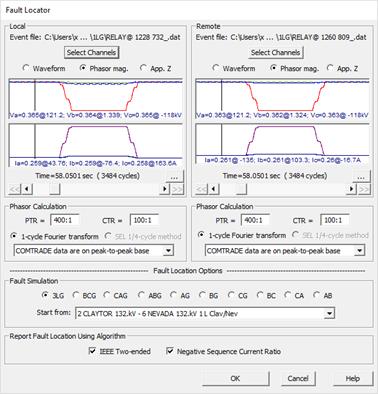
If you had selected two relay groups, the program will ask you to open two fault recording files.
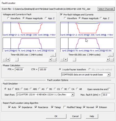
The Fault Locator dialog will appear with the display of relay quantities from the file(s) you selected.

Fault locator dialog box with one relay group selected

Fault locator dialog box with two relay groups selected
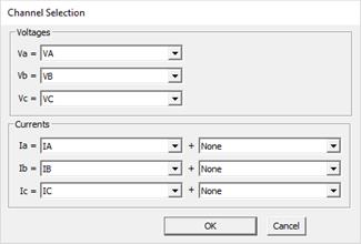
3. Select voltage and current channels.

You can select the voltage and current channels if the input file is a CEV, EVE, PQDIF or COMTRADE file.
For CEV, EVE and COMTRADE files only: the 2nd set of current channels can be selected when fault locator function is initialized from single relay group. The fault current detected by the relay will be the sum of the 1st and 2nd sets of current channels.
4. Specify relay voltages and currents.
Use the horizontal slider control beneath the waveform area(s) to select a narrow time window (1 cycle or ¼ cycle) over which the voltage and current phasors will be used in fault location.
If the fault recording file includes recorded data from pre-fault condition, mark the check box Pre-fault voltages and currents and select a suitable pre-fault time from the waveform area. This selection will allow you to utilize some fault location algorithms that rely on relay quantities from both pre-fault and fault periods (Pre-fault quantities selection is available only if you have chosen one relay location in step 1).
For COMTRADE files only: Specify in the combo box whether the waveforms are on peak-to-peak or rms base.
NOTE: You can also open a text file with relay voltages in kV (L-N) and current in A, separated by semicolons in the following format:
Va=xxxx@yyyy;Vb=xxxx@yyyy;Vc=xxxx@yyyy;Ia=xxxx@yyyy;Ib=xxx@yyyy;Ic=xxxx@yyyy
Where Va=, Vb=, Vc=, Ia=, Ib=, Ic= are required labels; xxxx are phasor magnitudes and yyyy are phasor angles in degrees.
Example of a text data file content:
Va=0.2@87.8;Vb=0.4@-27.2;Vc=0.4@-151.4;Ia=19.7@11.7;Ib=1.3@-2.6;Ic=1.3@17.8
5. Select fault location options.
Click on the Fault Type radio button. As you use the horizontal slider to select the fault voltages and currents, the program will highlight as default the radio button of the fault type that best matches the selected pattern of voltages and currents. You can overwrite this default value if desired.
Select the Fault location Start from relay group.
The two options below are available only if you have chosen one relay location in step 1
Select the upper limit of fault resistance amount to be applied in the search
Mark the check box Open remote line end to simulate in fault location the condition where the breaker on line remote end had already open in the fault.
6. Click OK to start fault location.
The standard windows File Save dialog box will appear to ask you to enter the pathname of fault location report file. The solution report is saved in Excel csv file and includes three sections:
- Summary of data files used in fault location study
- Selected relay voltages and currents data from recorded event
- Best matched fault sites with following details:
PCNT: fault location in percent of line impedance
DIST: fault location distance measured from LINE_FROM bus (DIST of zero will be printed in the report if the line length data attribute is not entered in the OLR file)
LINE_FROM, LINE_TO, KV, CKTID: End buses of the line, nominal kV and circuit ID.
Vx_M, Vx_A, Ix_M, Ix_A: Magnitude and angle of relay voltages and currents from simulation
TOTALOHM, TOTALMILES: calculated distance to fault from the relay location
FLT_TYPE, FLT_R: fault type and resistance in simulation
AUTO, APPZ, REACTANCE, TAKAGI, TAKAGIEX, ERIKSSON, NOVOSEL: flag indicating if the corresponding fault location algorithm was used in location the fault site.
The program also prints to the TTY windows a table with list of best matched fault cases.

Main Window
FAULTS MENU