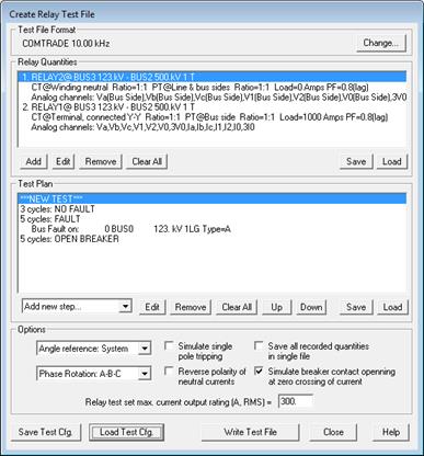
The Create Relay Test File command in the Main Window creates one or more files for relay testing. The relay test file contains voltages and currents for one or more short-circuit conditions that you simulated in OneLiner as well as pre-fault and post-fault states. The test files can be in one of the following formats: COMTRADE files, Doble SS1 files, comma delimited files (CSV), and tab delimited text files...
This command can be used to create a test file for relays at a single location, or it can be used to create multiple files for end-to-end testing.
TO CREATE RELAY TEST FILES:
1. Optional: Simulate the faults that you want to included in the test file.
You may want to test the relay with faults that should trip the relay as well as faults that should not trip the relay. You may alternatively create a sequence of faults that the relays may “see”, e.g., an intermediate fault near the remote bus, followed by a line-end fault.
2. Optional: Select a location on the one-line diagram where the test quantities will be recorded.
Click the right mouse button on either a relay group or on one end of a branch symbol. The selected symbol will become dotted red.
3. Select the Relay | Create Relay Test File command.
The Create Relay Test File dialog box will appear.

Optional: Press the ‘Load Test Cfg.’ Button to retrieve previously saved relay quantities and test plan in disk file.
4. Select test file format.
Click on ‘Change’ button in ‘Test File Format’ frame to select a file format. A dialog box will appear.
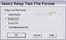
Select the output format by clicking on one of the radio buttons:
“COMTRADE” and enter sampling rate in the edit box to create a COMTRADE file (IEEE C37.111-1999 standard). Most test equipment can read this file format.
“Doble SS1” to create test file with Doble SSIMUL macros. This file format can be read by Doble ProTest software and by most test-equipment manufacturers (e.g., Omicron).
“Excel CSV” to create test file in CSV format. This file format is accepted by Microsoft Excel and other spreadsheet software.
“Text-delimited text file” to create a test file in text.
Press OK.
5. Click on ‘Add’ button in ‘Relay Quantities’ frame to specify which relay or relays are being tested.
If you highlighted a branch terminal or relay group in step 2, skip to step 2.
Step 1 : In the ‘Select Network Element’ dialog box that appears, select the branch terminal where you want to record currents and/or voltages for relay testing.
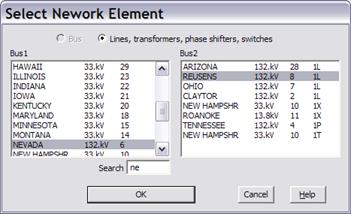
Press OK.
A dialog box will appear asking you to specify the relay on the selected branch terminal that you want tested.
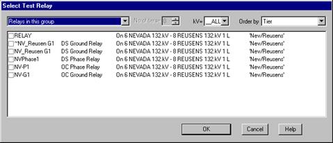
Step 2: Mark the check box in front of the relay that you want to test, OR click on the entry labeled RELAY to create a generic test file for relays at this location.
Press OK to close the Select Test Relay dialog box.
6. Specify relay test quantities:
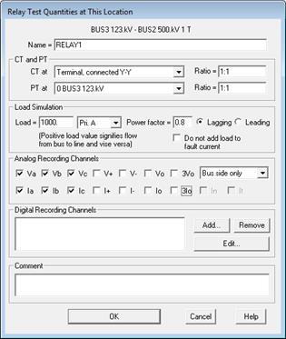
Enter a unique name to describe this set of test data. The name can be up to 44 characters long.
Select CT location and connection from the ‘CT at’ combo box. Enter CT ratio in the Ratio edit box to the right.
Specify PT location from the dropdown ‘PT at’ combo box. Enter PT ratio in the edit box.
Note: Select “N/A” in one of the above dropdown combo box if corresponding signal is not wanted in the output file.
Specify prefault load current or MVA and power factor in the edit boxes. Reference flow direction is from bus to line. Prefault voltage will be calculated according to the selection for the short-circuit ‘prefault voltage profile’ option. Select the check box ‘Do not add load to fault current’ to include in the test file the load current in the prefault state only.
Select voltage channels to be included in the test file. Available channels are phase and sequence quantities.
Select ‘Line side only’, ‘Bus side only’ or ‘Line and bus side’ voltage. Line side voltage will be recorded as zero in following situations: 1) Breaker open state; 2) Intermediate fault on transmission line with the relay end open.
Select current channels to be included in the test file. Available channels are phase and sequence quantities. Transformer neutral current and tertiary winding circulating current can also be selected if the relay CT is on a transformer.
Select reference angle and phase rotation for current and voltage quantities.
Skip to the ‘Click OK…’ paragraph at the end of this step if you are not exporting to a COMTRADE file
Specify COMTRADE digital recording channels: you can create COMTRADE digital channel for binary signals alongside with analog voltages and currents to control the relay test-equipment function during the relay test. Click on ‘Add’ to insert a new digital channel. The digital channel dialog will appear.
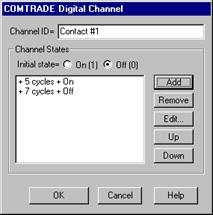
Enter channel ID
Enter channel initial channel state.
To insert a new state transition, press Add. A dialog box will appear.

Enter in the edit box the time interval since the last state transition. Press OK.
To remove a state transition: Highlight it in the list and press Delete.
To move a state transition up or down the list: Highlight it in the list and Press Up or Down.
To change the time interval between state transitions: Highlight it in the list and press Edit.
Press OK after entering all state transitions for the digital channel.
You will be back in the Relay Test Quantities screen.
To edit setting of a digital channel: Highlight it in the channel list and press Edit.
To remove a digital channel: Highlight it in the channel list and press Delete.
Enter comment in the edit box. Information you type in this box will appear in the COMTRADE header file.
Click OK .
Create Relay Test file screen will appear with a summary of relay test quantities you specified.
7. Specify additional set of test quantities or edit existing set.
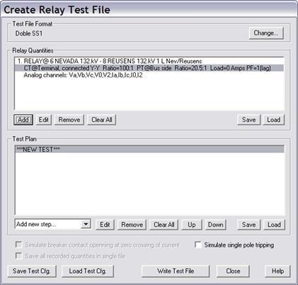
To edit setting of an existing test quantities set in the list, highlight it in the list and press Edit.
Skip the rest of this step if you are not planning to do end-to-end testing.
To perform an end-to-end test on a transmission line, the voltage and current test quantities at both ends of the line are required. To perform an end-to-end test on a 3-terminal line, the test quantities at all three ends of the 3-terminal line are required.
Click on ‘Add’ button in the ‘Relay Quantities to Record’ list. The Relay selection dialog box will appear.
Repeat step 5 and 6 to specify additional set of test quantities to record.
Click on Edit button to edit a relay quantities set.
Click on Remove button to remove the selected quantities set.
Click on Clear All button to remove all quantities sets.
Click on Save and Load button to save quantities sets to and read from a disk file.
8. Specify the relay test plan.
A relay test can have any number of steps. You can specify following system states in each test step:
•FAULT: Relay voltages and currents in a classical or simultaneous fault simulation will be recorded.
•NO FAULT: Simulated load currents (if specified) and pre-fault voltages will be recorded.
•BREAKER OPEN: Zero currents and pre-fault voltages will be recorded. If the ‘Force PT output to zero in Breaker Open state’ flag is checked for this set of relay quantities, zero voltage will be recorded.
Note: If you are creating a relay test file in Doble SS1 format, you can specify multiple tests in the same file. Each test starts with a ***NEW TEST*** entry.
Click on the ‘Add new step…’ dropdown list to add a new test step.
If you select NOFAULT… or BREAKER OPEN… a dialog box will appear for you to specify step duration.

Enter the step duration in the edit box. All durations are in cycles.
Press OK to close this dialog box. You will be back at the Create Relay Test file screen with updated test plan.
If you select FAULT… from the drop down list a dialog box will appear to select or specify the fault.
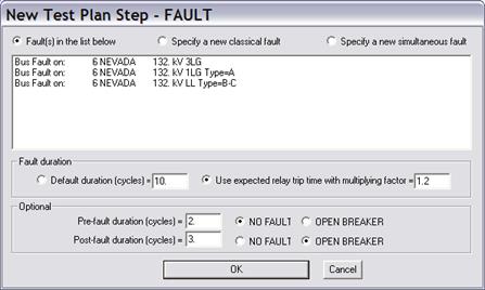
TO USE EXISTING FAULT SIMULATION IN FAULT STATE
All the faults you simulated prior to this command are available within the list box.
Click on radio button Fault(s) in the list below and select in the list box the entries you want to use.
Note: The program will create the same number of fault states as the number of faults you select in the list.
TO SPECIFY NEW FAULT STATE
Click on radio button “Specify a new classical fault” or “Specify a new simultaneous fault”.
Select Fault duration option: “Fixed default duration in cycles” or “Use expected relay trip time in fault with a multiplying factor”.
When the “Use expected relay trip time…” option is selected, the program will simulate the relay operation in fault to determine duration of the fault state. If the relay does not trip in the fault, the default fault duration value you entered will be used. If the relay operating time is zero, duration of 1 cycle will be used.
(Optional) Enter nonzero pre-fault and post-fault duration to add these steps before and after each of the FAULT step you specified. All durations are in cycles.
Click on OK to close the dialog box
If you selected ‘SPECIFY CLASSICAL FAULT…’, a Select Network Element dialog box will appear.
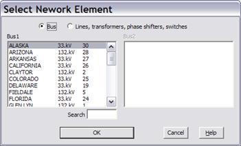
Use controls in the dialog box to select a bus or branch where the fault will take place and click OK. The Specify Classical Fault dialog box will appear. Use controls in the dialog box to select specify classical faults for relay testing.
If you selected ‘SIMULTALNEUOS FAULT…’, the Test Plan Step – FAULT will appear.
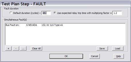
Click on + to add new simultaneous faults.
Click on - to remove a fault from list.
Click on … to edit fault parameters.
Click on Save or Load button to save or read fault specification in disk file. Click OK when done.
Specify the fault duration option. See instructions above.
Press OK to close this dialog box.
You will be back at the Create Relay Test file screen with updated test plan.
Press Edit to edit parameters of a test step.
Press Remove to remove the selected test step.
Press Clear All to remove all test steps.
Press Up and Down to rearrange test steps sequence.
Press Save and Load to save test plan to and read from a disk file.
9. Test file options:
Select angle reference. If something other than System is selected phasor angle of all test quantities will be rotated so that angle of the selected quantity will be zero.
Select system phase rotation ABC or ACB for all test quantities in the test file.
Select ‘Save all recorded quantities in single file’ check box to create a single file with all recorded quantities. If this option is not selected, the program will create separate test file for each set of test quantities.
Click on ‘Simulate breaker contact opening at zero crossing of current’ to align signal transition from Fault state to Open Breaker state exactly at a current zero crossing. Note: this option can be selected only when creating COMTRADE files.
Click on ‘Simulate single pole tripping’ to ask the program to record transition from Fault to Open Breaker state only for the faulted phases.
Click on ‘Reverse polarity of neutral currents’ to add 180 degree to phase angle of all neutral current quantities in the test file.
Enter ‘Relay test set max. current output rating’ in edit box. When this value is not zero the program will apply a PTR and CTR scaling factor to keep current magnitude below this rating.
10. Write the test files.
Click on ‘Write test file’ button when you finish entering all recorded quantities setting and test plan.
A standard File Save dialog will appear. Use the controls in this dialog to enter test file name and location.
The program will ask for one file name for each set of test quantities you specified. COMTRADE header file (.hdr) and configuration file (.cfg) will have the same name you assigned to the data file (.dat) in the File Save dialog box.
After all test files have been created, the program will display an information message box.

Click OK to go back to the Create Test File screen.
11. Save test configuration in disk file.
Click button ‘Save Test Cfg.’ to store selected relay quantities and test plan in disk file. The file will have extension .TCF
12. Specify another test plan or exit.
Repeat steps 5, 6, 7 and 8 to create anther set of test files.
Press Done to exit this command.
Main Window
RELAY MENU