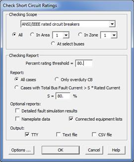
The Check | Circuit Breakers and Devices Short Circuit Rating command in the Main Window checks the short circuit ratings of circuit breakers, fuses, reclosers and disconnect switches against fault currents they need to carry and interrupt. The checking algorithm is based on either ANSI or IEC standards. The output can be written to the TTY Window or to a CSV or text file.
Note: This command requires a license for the ASPEN Breaker Rating Module, an optional add-on module that is not included in the regular ASPEN OneLiner software. Please write to info@aspeninc.com for licensing info.
TO CHECK CIRCUIT BREAKERS AND DEVICES RATINGS AGAINST FAULT CURRENTS:
1. Select the Check | Circuit Breaker and Devices Short Circuit Rating command.
A dialog box will appear.

2. Specify checking scope. Click on:
ANSI/IEEE rated circuit breaker: To perform fault calculation and check ANSI/IEEE-rated breakers using applicable ANSI/IEEE standards.
IEC rated circuit breakers: To perform fault calculation and check IEC-rated circuit breakers using applicable IEC standards.
Fuses, reclosers and switches: To perform fault calculation and check rating of fuses, reclosers and switches.
Note: At the time of this writing, the option for checking Fuses, reclosers and switches is not yet functional.
3. Specify checking extent. Click on one of the three radio buttons:
All: To check all the breakers in the network.
In Area: And select an area number in the drop-down list to check all the breakers in that area.
In Zone: And select a zone number in the drop-down list to check all the breakers in that zone.
At selected buses: The program will ask you to select the buses when you press OK.
4. Enter the rating threshold in percent.
The checking report gives warnings when the interrupting duty or momentary duty exceeds this percentage.
5. Specify the report coverage. Click on:
All cases: Include in the report all breakers checked whether or not their duty exceeds the threshold.
Over duty devices only: Include in the report only breakers with one or more warnings.
Cases with Total Bus Fault Current > S * Rated Current: Include in the report detailed checking result for a breaker only when (1) the interrupting duty computed using the bus fault current at the relay location exceeds S percent of the breaker’s interrupting rating, or (2) the momentary duty computed using the bus fault current at the relay location exceeds S percent of the breaker’s momentary rating. A large percentage, S, reduces the run time because fewer faults (line-out faults and close-in faults with end open) need to be simulated.
6. Specify the additional outputs to be included in the report. Mark:
Detailed fault simulation report to include in the report a table summarizing results of all the fault simulations that the program performed to check the selected breakers.
Breaker data to include in the report the data of all the breakers that were checked.
Connected device lists to include in the report lists of connected devices of the breakers that were checked.
7. Specify the output file format. Mark one or more of the following:
TTY: to generate a report in the TTY Window designed for human readability.
Text file: to produce a text report file designed for human readability.
CSV file: to produce a CSV-formatted report file. The CSV file contains the same information as the text file, but is designed for efficient computer processing. The CSV output file is required for the Comparison Program.
8. View and edit the breaker-checking options.
Click on the Options… button to display the breaker checking option screen.
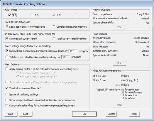
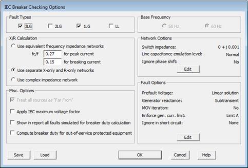
Depending on the standards you selected in step 2, you will see either the ANSI/IEEE Options dialog box or the IEC Options dialog box.
ANSI/IEEE checking options:

Fault types: Mark the check boxes under the Fault Types heading to specify the fault connections to be simulated. At least one fault connection must be selected.
X/R ratio calculation: Calculate the X/R ratio from separate X-only and R-only network or from complex Thevenin equivalent impedance at the fault location.
Warning: The second option may violate ANSI standards regarding asymmetrical fault current calculation.
Specify whether to use an increased rating (up to 15% more) for single-line-to-ground faults when checking breakers.
Note: The ANSI/IEEE standards for symmetrical-current rated breakers allow the use of a higher current rating for single-line-to-ground faults. No such provision is mentioned in the standards form total-current rated breakers. See Section 4.4 of the Breaker Rating Application Guide for details.
Specify the kV threshold, beyond which the voltage range factor K must be set to 1. Holding K at 1 has two important effects on breaker rating: (1) It makes the breaker’s interrupting capability a constant value, regardless of the operating kV. (2) It prevents the program from using an increased rating for single-line-to-ground faults – even if you have elected to do so. See Section 4.4 of the Breaker Rating Application Guide for details.
Note: The default is 121kV because ANSI/IEEE standards for symmetrical-current rated breakers stipulate that K must be 1.0 for breakers with maximum design kV of 121 or higher.
Mark the box “Apply scaling factor…” to instruct the program to scale the post-fault breaker current using the indicated ratio. This scaling effectively simulates faults with pre-fault voltage set equal to the breaker’s operating kV.
Mark the box “Set default breaker operating kV equal to flat pre-fault voltage profile pu” to instruct the program to make the default breaker operating kV to be same as the flat pre-fault voltage magnitude (which you can specify in the Faults | Option dialog box).
Note: This option affects only breakers that have operating kV field equal to the breaker bus’s nominal kV, which is the default value for this field. This check box is available only when flat pre-fault voltage profile is in effect.
Mark the box “Treat all sources as remote” to instruct the program not to consider ac decay in calculating breaker interrupting duties, regardless of the breakers’ Non-ac decay ratio.
Note: At or near generator bus, the short circuit current typically contains a significant ac decaying component. Selecting this option may cause the program to report higher than actual interrupting duties for breakers at these sites. To put it another way, the results for breakers near generators will be on the conservative side.
Mark the box “Ignore reclosing settings” to instruct the program to not to derate breakers that reclose after a fault.
Note: This option may violate ANSI standards regarding derating certain type of breakers for reclosing.
Mark the box “Show in report all faults simulated for breaker duty calculation” to instruct the program to include a full list of all faults that were simulated when calculating breaker duty. When this check box is unchecked, the breaker rating report will contain list of only faults in which the highest breaker percent duty was found.
Mark the box “Compute breaker duty for out-of-service protected equipment” to instruct the program to calculate breaker duty for in-service as well as out-of-service components in the protected equipment list. When this check box is unchecked, the breaker duty calculation will not be performed for out-of-service equipment.
IEC checking options:

Fault types: Mark one or more checkboxes under Fault Types heading to specify the fault connections to be simulated. At least one fault connection must be selected.
X/R ratio calculation: Select the equivalent frequency method or separate X-only and R-only network method for computing the X/R ratio. IEC standards recommend the equivalent frequency method. If you choose the equivalent frequency method, you must enter the ratio between the equivalent frequency and the base frequency fc/f for breaking current and peak current calculation. The ratio depends on the time from the initiation of short circuit and should be determined from the following table:
Time
(cycles)
fc/f
<
1
0.27
<2.5
0.15
<5.0
0.092
<12.5 0.055
Mark the Treat all sources as far from checkbox to instruct the program to use factor μ = 1 and κ = 1 in calculating interrupting current from a generator or motor source.
Note: At or near generator bus, the short-circuit current typically contains a significant ac decaying component. Selecting this option may cause the program to report higher than actual interrupting and peak duties for breakers at these sites. To put it another way, the results for breakers near generators will be on the conservative side.
Mark the Apply IEC maximum voltage factor checkbox to instruct the program to use the IEC voltage factor c that gives maximum short-circuit current. For medium and high voltage breakers with designed 1kV and above: c = 1.1
Mark the box “Show in report all faults simulated for breaker duty calculation” to instruct the program to include a full list of all faults that were simulated when calculating breaker duty. When this check box is unchecked, the breaker rating report will contain list of only faults in which the highest breaker percent duty was found.
Mark the box “Compute breaker duty for out-of-service protected equipment” to instruct the program to calculate breaker duty for in-service as well as out-of-service components in the protected equipment list. When this check box is unchecked, the breaker duty calculation will not be performed for out-of-service equipment.
9. Press OK.
If you selected to check breaker rating “At selected buses” in step 3, the Bus Selector will appear.
Use controls in the Bus Selector to select one or more buses. Documentation for the Bus Selector is in APPENDIX H: BUS SELECTOR.
A file-open dialog box will appear asking you to enter the output file name if you selected to output the results to a text file or CSV file.
Use the controls in the standard file dialog box to specify the name of the output file, and then press Save.
You should name all your output files with the .TXT extension, and all CSV files with the .CSV extension.
Main Window
CHECK MENU