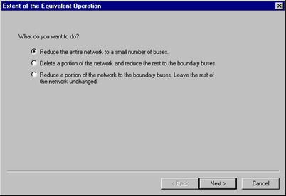
The Boundary Equivalent command in the Main Window computes the multi-port Thevenin equivalent for one or more buses in the network. At the end of this command, the equivalent network will appear on the one-line diagram. This command employs a “wizard” interface to guide you through the process of specifying the portion of the network that you want to eliminate or the portion that you want to retain.
TO COMPUTE A BOUNDARY EQUIVALENT:
1. Select the Network | Boundary Equivalent command.
The Boundary Equivalent wizard will appear. The first page will ask you what you want to do.

Choose one of the three choices and press Next.
The three choices are explained in the following.
OPTION 1: REDUCE THE NETWORK TO A SMALL NUMBER OF BUSES:
A typical application is to reduce the network to the terminal buses of a transmission line, so that the reduced system can be studied further using the EMTP.
1. Specify which buses to retain.
The wizard will ask you which buses you wish to keep.
Select the buses to be retained by highlighting their names in the list box on the left list box. Press the ‘à’ button to move the buses to the list box on the right.
You can alternatively click on the ‘…’ button to the right of the ‘à’ button to move a group of buses that satisfy certain criteria, such as zone or area membership. Please see APPENDIX H: BUS SELECTOR for more information on the ‘Add To Bus List’ dialog box.
If needed, add or remove bus from right list box using the “à” button and the “ß” button.
Repeat this step until the right list box has all the retained buses.
2. Mark the checkbox “Retain all existing equipment at these buses” if you wish to keep the original branches between the retained buses. Otherwise, the fictitious branches generated by the network-equivalence algorithm may subsume these branches.
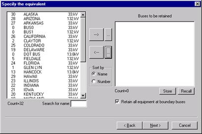
Press “Next >”.
Skip to the subsection “CONFIRM YOUR SELECTION AND FINISH BUILDING THE EQUIVALENT”
OPTION 2: DELETE A PORTION OF THE NETWORK AND REDUCE THE REST TO THE BOUNDARY:
A typical application is when your neighbor asks you for an equivalent of your company’s network at the company boundary. We assume that the file you are using has both your network and your neighbor’s. That is why you must delete your neighbor’s network before reducing the remainder (i.e., your network) to the boundary buses.
1. Specify which buses to delete.
The wizard will ask you which buses you wish to delete.
Select the buses to be deleted by highlighting their names in the list box on the left list box. Press the ‘à’ button to move the buses to the list box on the right.
Repeat this step until the right list box has all the buses to be deleted.
You can alternatively click on the ‘…’ button to the right of the ‘à’ button to move a group of buses that satisfy certain criteria, such as zone or area membership. Please see APPENDIX H: BUS SELECTOR for more information on the ‘Add To Bus List’ dialog box.
If needed, add or remove bus from the right list box using the “à” button and the “ß” button.
Repeat this step until the right list box has all the buses you want deleted.
The wizard should look something like this.
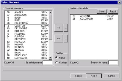
Press “Next >”
2. Check the boundary buses identified by the program.
This page lists the boundary buses in a list box on the right. The equivalent network will contain only these buses.
If needed, add or remove bus from the list of boundary buses using the “à” button and the “ß” button.
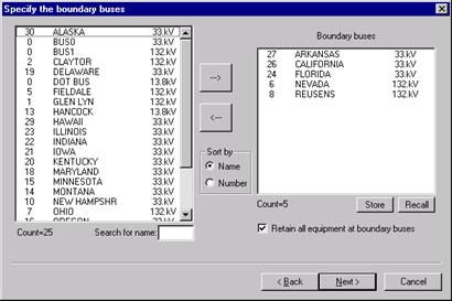
3. Mark the checkbox “Retain all existing equipment at these buses” if you wish to keep the original branches between the boundary buses. Otherwise, these branches may be subsumed by the fictitious branches generated by the network-equivalence algorithm.
Press “Next >”
Skip to the subsection “CONFIRM YOUR SELECTION AND FINISH BUILDING THE EQUIVALENT”
OPTION 3: REDUCE A PORTION OF THE NETWORK TO THE BOUNDARY AND LEAVE THE REST OF THE NETWORK UNCHANGED:
A typical application is when you have a file that contain your system and your neighbor’s system, and you wish to reduce your neighbor’s system to an equivalent network at the boundary and leave your own system unchanged.
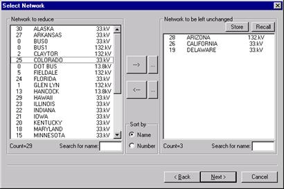
1. Specify the network to be left unchanged.
The wizard will ask you to specify the network to be left unchanged.
Select the buses to be left unchanged by highlighting their names in the list box on the left list box. Press the ‘à’ button to move the buses to the list box on the right.
Repeat this step until the right list box has all the buses to be left unchanged.
You can alternatively click on the ‘…’ button to the right of the ‘à’ button to move a group of buses that satisfy certain criteria, such as zone or area membership. Please see APPENDIX H: BUS SELECTOR for more information on the ‘Add To Bus List’ dialog box.
If needed, add or remove bus from the right list box using the “à” button and the “ß” button.
Repeat this step until the right list box has all the buses you want to be left unchanged.
The wizard should look something like this.
Press “Next >”
2. Check the boundary buses identified by the program.
This page lists the boundary buses in a list box on the right. The equivalent network will contain only these buses.
If needed, add or remove bus from the boundary bus list using the “à” button and the “ß” button.
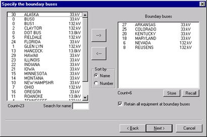
3. Mark the checkbox “Retain all existing equipment at these buses” if you wish to keep the original branches between the boundary buses. Otherwise, the fictitious branches generated by the network-equivalence algorithm may subsume these branches.
Press “Next >”
CONFIRM YOUR SELECTION AND FINISH BUILDING THE EQUIVALENT:
The following steps are common to all three options.
1. Check the information displayed at the top of this page. If it is not correct, press the “<Back” button to go back to the previous pages and fix the problem.
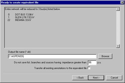
2. Enter the full path name of the output file.
The output file is a binary data file (with extension .OLR) that will contain the reduced network.
Enter the file name in the edit box. Alternatively, press the “Browse” button to specify the file name and location with the standard File-Save dialog box.
3. Specify the impedance threshold for the equivalent branches.
An equivalent branch with per-unit impedance greater than this number will be ignored.
4. Check the box “Transfer all existing annotations to the equivalent file” to keep all existing text annotations in the equivalent network.
Note: Annotations that are attached to retained equipment and annotations that are located inside the selected region on the 1-line diagram are always copied to the equivalent network.
Press “Next >”
5. Finished.
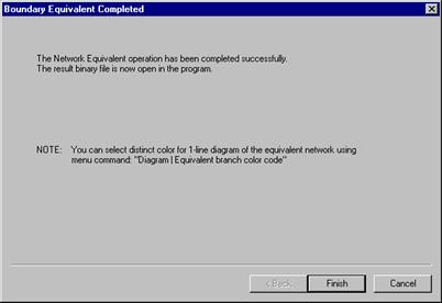
This final page tells you that the equivalent network has been created successfully.
Press “Finish”
The output file name will appear at the top of the main window, and the one-line diagram of the equivalent network will appear.
Main Window
NETWORK MENU