The Batch Fault Simulation command in the Main Window lets you simulate bus faults, line-end faults and line-out faults at one or more buses and output the results to a text file or CSV file.
TO SIMULATE FAULTS IN BATCH MODE:
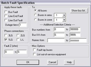
1. Select the Faults | Batch Fault Simulation command.
A dialog box will appear asking you to specify the faults.

2. Select the fault type. Click on one or more of the following fault types that will be applied to the buses you select in step 5:
Bus Fault: To apply a fault at the bus.
Line-end fault: To apply a fault at the far end of each of the branches incident on the bus with the far end of each bus disconnected.
Line-out fault: To apply a fault at the bus with each of the nearby branches taken out of service one at a time. The nearby branches are those within the tier limit you specify. Enter in a tier limit in 'Outage tiers'. When the tier limit is 1, only the branches incident on the bus will be taken out of service.
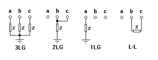
3. Select the phase connection. Click on one or more of the following:
3LG: 3 phase to ground.
2LG: 2 phase to ground.
1LG: 1 phase to ground.
L-L: Line to line.

4. Enter in the fault impedance in 'Fault Z (ohm)'.
The fault impedance, Z, is shown in the above figure.
5. Select the buses to be faulted. Click on:
All buses: To apply the selected faults to all the buses.
Buses in area: And select an area in the dropdown list box to apply the selected faults to all buses in that area.
Buses in zone: And select a zone in the dropdown list box to apply the selected faults to all buses in that zone.
The buses in the system, or buses in an area or zone, can be further limited by limits on bus number, nominal kV, and bus name.
Bus numbers from/to: Buses to be faulted must have a number within this range.
Bus kVs from/to: Buses to be faulted must have a nominal kV within this range.
Names from/to Buses to be faulted must have a name within this range.
Note: For the bus-name range, please note that the sort order is ASCII, where all upper case letters precede all lower case letters.
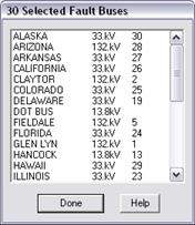
6. Press 'Show bus list' to view a list of buses that will be faulted.
A dialog box will appear displaying a list of buses that satisfy the selection criteria that you have specified. The total number of buses listed is shown at the top of this dialog box.

7. Mark the 'Fault tap buses' check box to fault tap buses.
8. Mark the ‘List out-of-service equipment’ to generate a report on all the out-of-service equipment at the beginning of the report file.
9. Press OK.
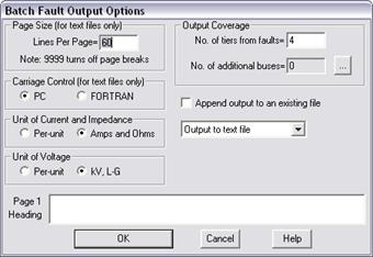
Another dialog box will appear, asking you to specify the output parameters.

10. Enter the number of lines per page in 'Lines Per Page'.
Enter the maximum number of lines that fit on a page. Enter 9999 to omit page breaks. This parameter is ignored if the output file is CSV formatted.
11. Enter the number of output tiers in 'No. of tiers from fault'.
The output of a fault always begins with a summary that shows the fault currents, Thevenin impedances and the X/R ratio. Following the summary are one or more bus-oriented outputs. Each of these shows the bus voltage before and after the fault. It also shows the currents flowing to generator, load, shunts, and branches that are connected to the bus. The extent of the bus-oriented outputs is controlled by the tier limit, which can be:
-1: Suppresses all tier-limited bus outputs.
0: Only the faulted bus is included in the tier-limited bus outputs.
1: The tier-limited output includes the faulted bus and its immediate neighbors.
The tier-limited output is followed by outputs for the “additional buses” specified.
12. Click on the button labeled “…” to select additional buses for the output.
Use the bus selector controls to build a list of buses that you want to include in the fault summary. See APPENDIX H: BUS SELECTOR for more information on the Bus Selector. Click OK when done.
The number of additional buses will be shown in a read-only edit box left of the button.
13. Select the carriage control. Click on:
PC: If the file will be sent to a printer that expects the PC escape control characters.
FORTRAN: If the file will be sent to a printer that expects FORTRAN control characters in the first column of each line, e.g., blank for line feed, 1 for new page.
This option is ignored if the output file is CSV formatted.
14. Select the output units.
In the “Unit of current and impedance” group box, press the "p.u." radio button to display currents and impedances in per unit, or the “Amps and ohms” radio button to display currents and impedances in physical units.
In the “Unit of Voltage” group box, press the "p.u." radio button to display bus voltages in per unit, or the “kV, L-G” radio button to display voltages in kV, line-to-ground.
15. Enter the heading on page 1 of the report 'Page 1 Heading' edit box.
16. Select the output file type in the drop-down list box: a text file or a CSV-formatted file.
17. Mark the check box labeled "Append output to an existing file" to append the output to an existing text file.
If this check box is not marked, the report will be written a new file.
Use the controls in the standard file dialog box to specify the name of the output file. Use extension ‘.txt’ for a text report and ‘.csv’ for a CSV formatted report. Press OK.
The program will show you the contents of the output file in the Text Report Viewer (for a .txt file) or in your spreadsheet program (for a .csv file) at the end of the simulation.
Main Window
FAULTS MENU