Q: How do I model a transformer with these parameters?
Primary tap: 125kV line-to-line, wye connected with grounded neutral.
Primary nominal kV: 115kV
Secondary tap: 14.4kV line-to-line, wye connected with grounded neutral.
Secondary side nominal kV: 13.8kV
Impedance: 6.0% based on a 15MVA base, with the primary and secondary taps at 125kV and 14.4kV, respectively.
A: We will let Bus1 115kV and Bus2 13.8kV to be the transformer model primary and secondary bus, respectively. All the transformer parameters can be entered into the program as they are.
Q: How do I adjust the transformer impedance if the impedance given by the manufacturer was measured at different voltage taps than those being used?
A: Experimental evidence indicates that the per-unit short-circuit impedance increases with the voltage tap, but there is no simple analytical formula to convert the impedance from one voltage tap to another. The most common assumption is that the per-unit impedance remains constant at all voltage taps. One may also compute the impedance using interpolation if the impedance is known at two or more voltage taps.
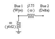
Q: I have a wye-delta transformer that is modeled by a branch and a shunt in my old short circuit program (Figure B.1). The nominal kVs are 115 and 69. How do I model this transformer in ASPEN OneLiner and what value should I use for the infinite impedance?

Figure B.1: The equivalent circuit of a 2-winding wye-delta transformer. The figure shows the positive- and zero-sequence impedances in percent. The zero-sequence impedances are enclosed in parentheses.
A: Use these parameters for the transformer: (We assume the per-unit impedances have already been adjusted to the appropriate MVA base.)
Winding configuration: Wye-delta with delta leading or lagging
Positive-sequence impedance: R+jX = 0.0+j0.0575 pu
Zero-sequence impedance: R0+jX0 = 0.0+j0.0462 pu
BUS1 tap voltage: 115.0 kV
BUS2 tap voltage: 69.0 kV
That's all. There is never a need to specify infinite impedances or special shunts for 2- winding transformers in OneLiner. The program automatically creates the appropriate equivalent circuits based on the winding configuration and the values of R, X, R0 and X0 given.
Q: How do I get the zero sequence impedance parameters values of a wye-wye-delta transformer from a IEEE 57.12.90 transformer test report?
A: IEEE 57.12.90 standard specifies following zero sequence tests:
Zero sequence voltage source is applied between the Primary and Neutral terminals, secondary terminals are shorted to Neutral to measure the impedance Z1Ns. This is the OneLiner Zps0 parameter.
Zero sequence voltage source is applied between the Primary and Neutral terminals, secondary terminals are left open to measure the impedance Z1No. This is the OneLiner Zpt0 parameter.
Zero sequence voltage source is applied between the Secondary and Neutral terminals, primary terminals are left open to measure the impedance Z2No. This is OneLiner Zst0 parameter.
Some test reports provide the zero sequence impedance test results as a T-equivalent circuit of the transformer. You can enter the test data directly in the OneLiner model as the “Classical ‘T’ model impedances” parameters.