 on the Device Palette.
You can add new equipment to the system by selecting the equipment type from the device palette and dropping a new device on the diagram. You will learn in the following how to create new buses and lines. Similar procedures apply to other types of equipment.
ADDING A NEW BUS:
1. Select command View | Device Palette to show the Device Palette if it is not already visible
Click the New bus button  on the Device Palette.
The cursor will change into a cross with a bus symbol attached to it.
2. Click on an empty space in the diagram to place the new bus.
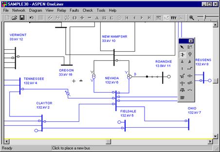
A dialog box will appear. The parameters in the bus dialog box are those of the last bus.
3. Modify the bus data.
Enter “New Bus” in the edit box labeled 'Name'.
Enter “33” in the edit box labeled 'Nom. kV'.
Change the area number to 1, and the zone number to 1.
Change location to “NEW”.
The Bus dialog box should look like this.
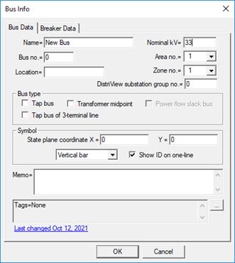
Note: The second page of the bus dialog box (not visible), labeled 'Breaker Data', is for circuit breaker information. The breaker data are used by the ASPEN Breaker Rating Module (an optional module of ASPEN OneLiner) to evaluate the adequacy of the breaker interrupting rating.
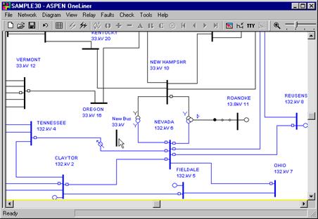
4. Press OK.
The dialog box will disappear and a new bus will appear at the location you selected in step 2.
ADDING A TRANSMISSION LINE:
You will now add a new transmission line between the new 33 kV bus and the Vermont 33 kV bus.
1. Click the New line button  on the Device Palette.
The cursor will change into a cross with a line symbol attached to it.
2. Click the left mouse button on the Vermont 33 kV bus. Without releasing the left button, move the mouse toward the “New Bus”. A line symbol will appear with one end attached to Vermont 33 kV bus. The other end of the line will move with the cursor.
When the cursor is near the “New Bus 33kV” bus, the bus symbol will turn dotted red. Release the mouse button.
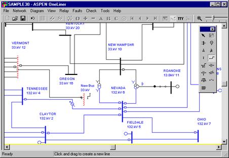
A dialog box will appear.
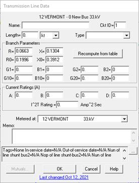
By default, the line data is set equal to that of the previous line object. That is why the line impedances are already set to a nonzero value. (You can change this behavior in the Network tab of the File | Preferences dialog box.)
3. Give this line a reactance of 0.1 per-unit in the positive sequence and 0.3 per-unit in the zero sequence.
Type “0.1” in the edit box labeled 'X'.
Type “0.3” in the edit box labeled 'X0'.
4. Press OK.
A new line will appear between the selected buses.
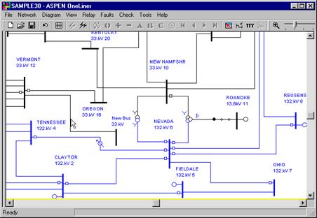
5. Press the <Esc> key on your keyboard to exit from the Add-Equipment mode.
The mouse cursor will change back to the normal arrow cursor.