In version 14, we added an “in-service date” and an “out-of-service date” to most network objects, including generator units, load units, shunt units, voltage controlled current sources, switched shunts, lines, series capacitors/reactors, transformers, phase shifters, switches and dc lines. In version 15, these attributes are made available to relay objects as well, including overcurrent relays, distance relays, fuses, reclosers, differential relays and voltage relays.
The in-service date is the date on which the equipment is put in service, and the out-of-service date is the date on which the equipment is taken out of service. Initially the in/out-service dates of all the network elements are set to “N/A”, meaning that they are not available.
You can enter one or both dates to account for commissioning of new equipment, retirement of old equipment, and temporary outage for maintenance and other reasons. There is no requirement that the in-service date precedes the out-of-service date, or vice versa.
The in/out-of-service status of relays and logic schemes is indirectly affected by the status of the network equipment on which they reside. For example, when a transformer is taken out of service because of the in/out-of-service dates, the program will automatically treat the protective equipment on the transformer as being inactive.
We recommend that you update the equipment’s status (in-service or out-of-service) so that it is consistent with the in/out-of-service dates. For instance, if the study date is now, then a transformer that is going to be taken out of service in the future should have an ‘active’ status.
The in/out service dates of network equipment are utilized by three commands in the Main Window:
•File | Save Copy for New Study Date, and
•Check | Network by Study Date
Please refer to the documentation of these commands for more information.
Tags are unrelated to the in/out-service dates, but when use together, they make a great project management tool. Consider the commissioning of a new generator. The project may involve the activation of a new generator, a step-up transformer, and the associated protective relays. To manage this project, we suggest you do the following:
1. Model the generator, step-up transformer and relays on the on-line diagram.
2. Apply the same tag to both the generating unit and the transformer.
3. Give both the generating unit and the transformer a future in-service date.
4. Take both the generator and the transformer out of service.
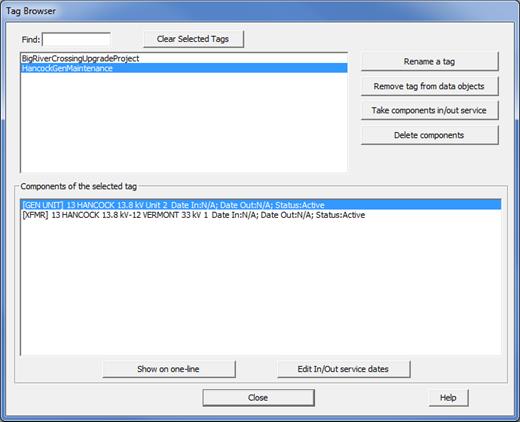
The new Network | Tag Browser command helps you visualize and manage these projects. Here is a sample screen for the components of a tag called “HancockGenCommissioning”. In fact, steps 3 and 4 can be carried out within this Browser, with the “Take components in/out service” button and the “Edit In/Out Service Date” button.
