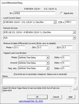
OneLiner simulates line differential relay operation by computing the residual of all the current inputs in secondary amps. A trip will be reported when this current exceeds the minimum pickup threshold.

The following are instructions to enter the data for a line differential relay:
1. Enter the identification data.
ID: Enter a name with up to 20 characters for the relay. We recommend that you include in the ID certain mnemonics that identifies the relay type and function. For example, you may want to begin the ID with the IEEE number for the protective relay element function. The ID only has to be unique among differential relays in the same relay group.
2. Enter local current input parameters.
CT location: Select current transformer location in the dropdown list box. The list box includes relay groups found in vicinity of this relay.
CT ratio: The CT ratio is defined to be the primary/secondary turns ratio of the current transformer. You can either a number value or a ratio in the form of xxx/yyy or xxx:yyy. For example, for a 1200: 5 amperes CT, enter one of the following: 240, 1200/5 or 1200:5.
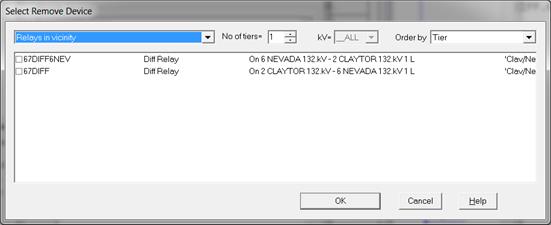
3. Select remote device: Choose Select remote device… in the dropdown list box. The device selection dialog box will appear with list of all line differential devices found in the vicinity of this relay:

Mark the check box next to the device you want to use in the differential protection scheme. Press OK. The device will now be listed as selected in the list box.
Note: The program will automatically assign this differential relay to list of Remote devices of the relay you had just selected.
4. Select second remote device: If the differential protection zone include 3rd line terminal repeat step 3 above to select the 2nd remote device
5. Enter minimum enable differential currents: Phase, 3Io and 3I2 in secondary amperes. The program will report differential relay pickup in fault simulation if and only if at least one of the differential currents exceeds the specified threshold.
6. Tapped Load Coordination.
Enter tripping delays in seconds for the purpose of coordinating differential relay tripping with phase overcurrent, ground overcurrent (3Io) and negative sequence (3I2) overcurrent protection at substation at a tap bus inside the differential protection zone.
7. Signal only.
Mark the check box if the differential relay is part of the logic scheme, and it is not used to trip any circuit breakers directly.
8. Enter a memo.
The memo is for any notes you wish to keep for this relay. It can have up to 512 characters.
Click on the … button near the upper right corner of the text area below the Memo field to open the Supplemental Object Properties dialog box with a data grid to enter data for the following data fields:
9. In/Out of service date: Click on the … button and enter the desired dates. See the Details and Techniques section “In/Out of service and tags” for more information.
10. Asset ID: An identifier for facilitating data exchange with external databases. The asset ID can have up to 127 characters.
11. Tags: Enter list of tag strings separated by semicolon. The tags are for organizing objects that are related for some purpose. Please see documentation for Network | Apply Tag for more information.
12. User-defined fields: These are custom data fields that are defined by the user. Please see documentation for File | Preferences for information about how to specify the template for these data fields.