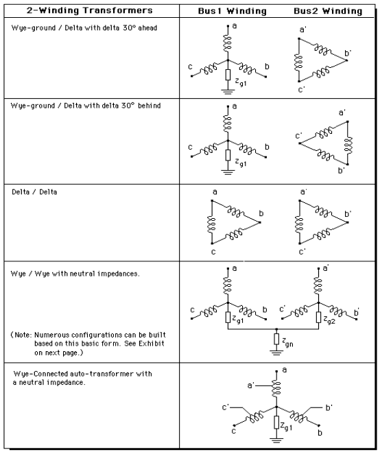
The program offers 2-winding transformer models in five basic configurations shown in figure 4.6. Note that in the case of a wye-delta transformer, the wye-connected winding is always on the Bus1 side.
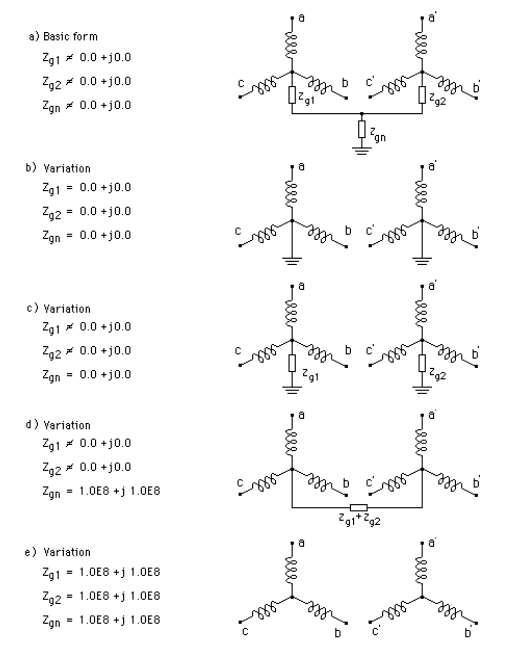
A number of variations can be derived from these five basic configurations by varying the grounding impedances. Figure 4.7 shows how this can be done for the basic configuration with two wye connected windings.

Figure 4.6: Basic two-winding transformer configurations.

Figure 4.7: Four variations of the basic wye-wye configuration. Note that infinite impedance is signified by the value 1.0E8 + j1.0E8.
In addition to the transformer winding configurations of Figure 4.6, the program also supports three zigzag winding configurations:
Zigzag-wye with wye leading 30 degrees
Zigzag-wye with wye lagging 30 degrees
Zigzag-delta (with no phase shift)
In these three configurations, the zigzag winding is always on the Bus1 side.