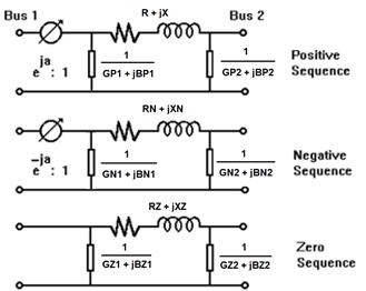
The phase shifter model for both short-circuit and power-flow studies is shown below. The impedances and phase shift angle are specified by the user. The impedance can be adjusted as a function of the shift angle, though an impedance-correction table.
An automatic control feature in the Power Flow Program adjusts the shift angle to control the MW flow through the phase shifter. The impedances are adjusted automatically if an impedance-correction table is in use.

Figure 4.3: Phase shifter model. "a" is the phase shift. A positive value causes the voltage angle of Bus1 to lead that of Bus2 in the positive sequence. R+jX is the leakage impedance, GP1+jBP1 and GP2+jBP2 are the magnetizing admittances in the positive sequence on bus 1 and bus 2 sides. The parameters RN+jXN, GN1+jBN1 and GN2+jBN2 are defined similarly in the negative sequence. The parameters RZ+jXZ, GZ1+jBZ1 and GZ2+jBZ2 are defined similarly in the zero sequence.