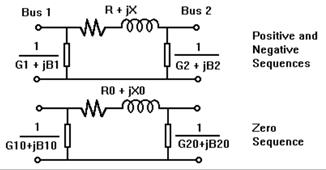
Each transmission line is modeled as a pi-circuit. See figure below. The shunt admittances at the two ends of the line can be different. The unbalanced shunts can be used to model reactors or capacitors that are switched on and off with the line. However, lines with unbalanced shunt admittances cannot be mutually coupled to other lines.

Figure 4.2: The transmission line model. In the positive and negative sequence, R+jX is the series impedance, and G1+jB1 and G2+jB2 are the shunt admittances. The parameters R0+jX0, G10+jB10 and G20+jB20 are defined similarly in the zero sequence.
A series capacitor/reactor is a simplified line with a capacitor or reactor between the two terminals. The reactances and the resistances X, R and X0, R0 are assumed to be the same.
When a series capacitor is modeled with MOV protection , the overall impedance of the MOV/capacitor assembly is a function of the protective-level current, defined as Vpk/(1.414*X), where Vpk is the maximum capacitor voltage maintained by the presence of the MOV, and X is the reactance of the capacitor bank. The protective-level current is typically 2.0 to 2.5 times the rated current of the capacitor bank. This model of the MOV-protected series capacitor was originally proposed by Dan Goldsworthy*.
The simultaneous-faults logic in OneLiner was modified to handle the MOV-protected series capacitors based on the Goldsworthy model. The solution is done in the phase domain (and not in the sequence domain) because the MOVs on the three phases of a series capacitor can have unequal impedances in an unbalanced fault. The short-circuit solution has to be iterative because the MOV characteristics are nonlinear. You can turn on or off the iteration logic for simulating MOV-protected capacitors using the Fault Simulation tab of the File | Preferences dialog box.
*D.L. Goldsworthy, “A linearized Model for MOV-Protected Series Capaitors,” IEEE Transactions on Power Systems, Vol. PWRS-2, No. 4, November 1987.